

The DOI matches its Crossref record; 27 of the 29 references it cites were found in a registry or an index; none of the 6 sources its claims cite is checked for support yet.
Simulation-Assisted Design of a Power Stack for Improving Static Current Sharing Among Three IGBT Modules Connected in Parallel
Open accessAbstract
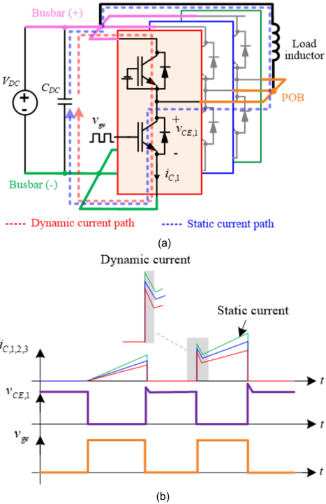
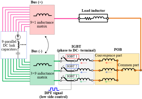
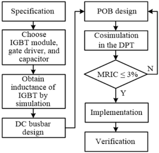
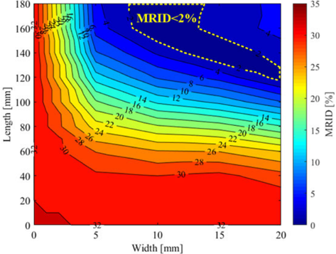
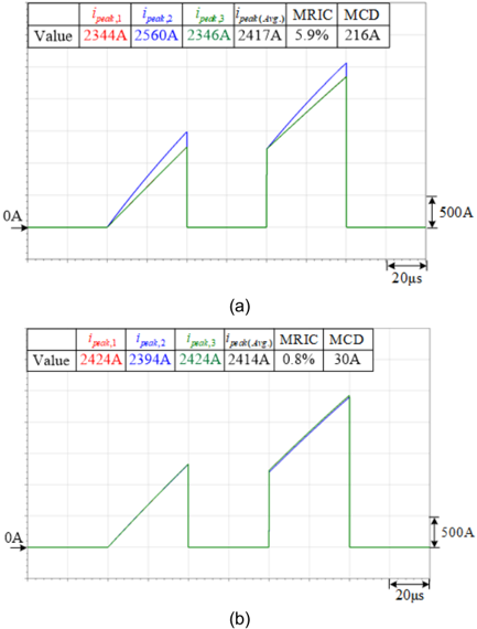
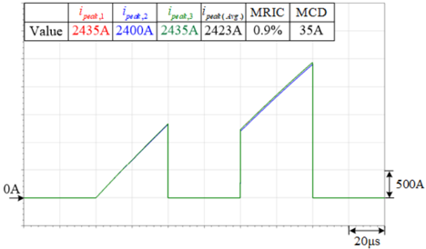
In this study, cosimulation with Q3D and Simplorer were adopted to design a single-phase power stack with equal output current on three paralleled IGBT modules in high power application, therefore, the derating of total current will be reduced, which can improve the current utilization and power density of power stack. The performance of the designed stack was verified using a double-pulse test (DPT). The circuit used in the DPT regarded the power stack output current as static current, which is a critical index to evaluate current sharing. The static current sharing among the IGBT modules was mainly dependent on the stray inductance of the DC busbar, IGBT modules, and phase output bar (POB), which is used to connect the IGBT modules to load, in parallel paths of the power stack. Cosimulation was performed to determine the stray inductance of the IGBT modules, DC busbar and POB, and a constant-current-slope method was used to verify the inductance. Subsequently, design the shapes of DC busbar and POB for attaining maximum ratio of imbalanced current (MRIC) of the three IGBT modules is within 3% under 200% (2400A) rated current. The cosimulation results indicated that the MRIC of the current paths in power stack were 0.8%. Finally, three IGBT modules and a gate driver were used to construct power stack with 1000V DC link. The experimental results obtained by DPT indicated that the MRIC was 0.9% under 200% rated current, demonstrating the effectiveness of the proposed stray inductance design method.
Overview
CoChat Summary
TL;DR
A simulation-assisted design method using Q3D–Simplorer cosimulation is proposed to equalize stray inductance in the static current paths of three paralleled IGBT modules in a single-phase power stack. The designed T-type phase output bar (POB) achieved a maximum ratio of imbalanced current (MRIC) of 0.8% in simulation and 0.9% experimentally under 200% rated current.
Key findings
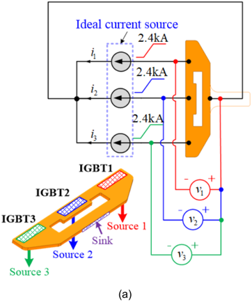
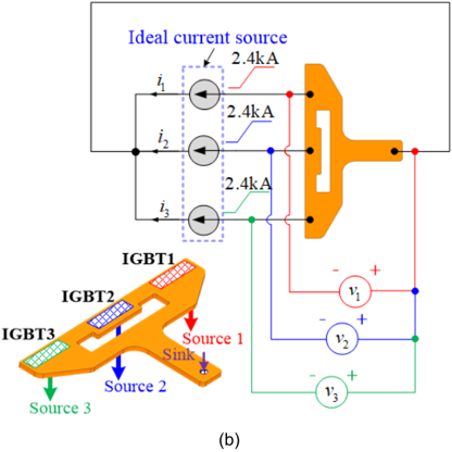
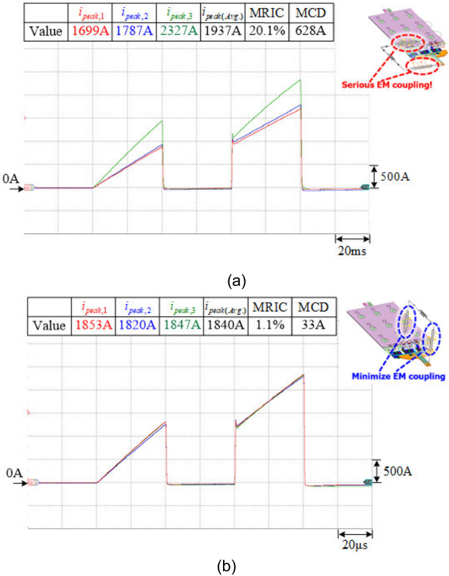
- The proposed POB reduced current imbalance compared with a traditional POB: cosimulated MRIC was 0.8% versus 5.9%, and maximum current difference (MCD) was 30 A versus 216 A.
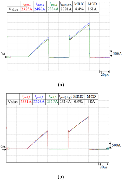
- In the double-pulse test (DPT), the proposed POB achieved an MRIC of 0.9% under 200% rated current (2400 A per IGBT module), with MCD decreasing from 161 A to 38 A when replacing the traditional POB.
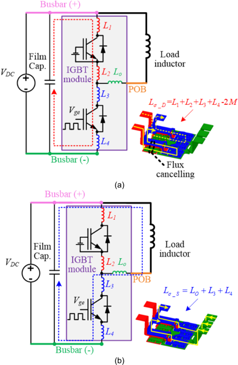
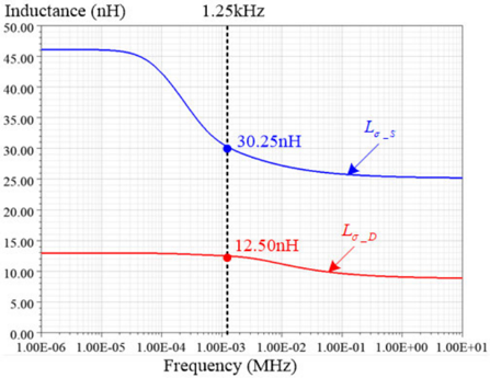
- Stray inductance verification showed the IGBT module static-path inductance was measured at 36.5 nH versus 30.3 nH simulated; the proposed POB simulation and experimental stray inductances matched with maximum error less than 3.1%.
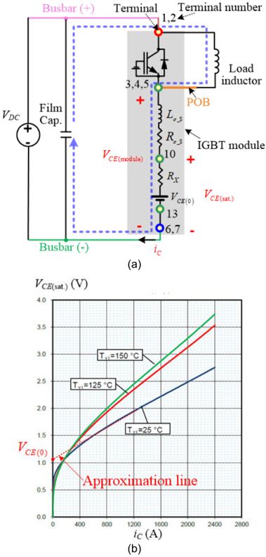
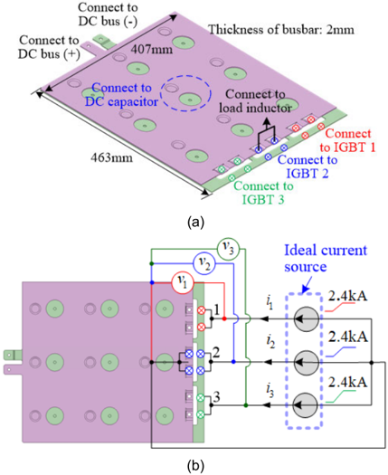
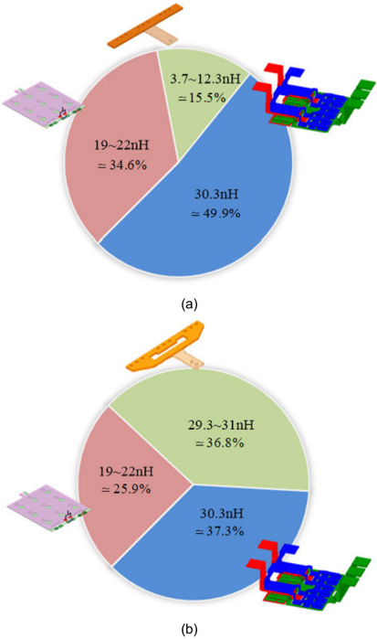
- The DC busbar stray inductances along the three paths were 22 nH, 19 nH, and 22 nH, and the IGBT module stray inductances represented nearly 50% of the total, giving them an important influence on static current balancing.
Methods
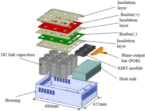
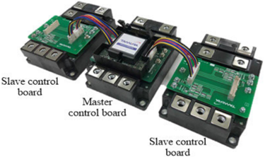
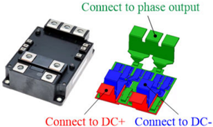
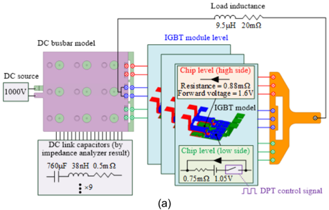
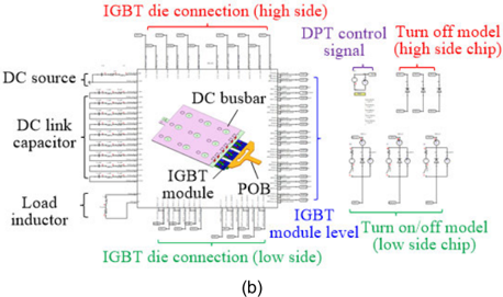
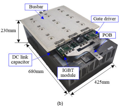
- Q3D and Simplorer cosimulation were used to design a laminated DC busbar and a T-type POB for a single-phase power stack containing three paralleled Mitsubishi CM1200DW-34T half-bridge IGBT modules (1200 A rated), a 1000 V DC link, nine film capacitors of 760 µF each (6840 µF total), and a single gate driver.
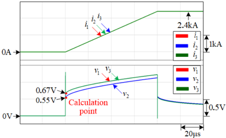
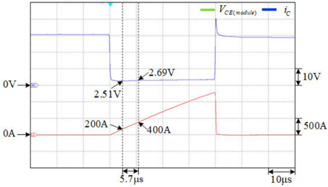
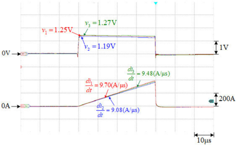
- Stray inductance was extracted using a constant-current-slope method from 0 to 2400 A in 80 µs per path; cosimulation used an ideal gate driver, a 9.5 µH load inductor, and a total output current of 7200 A at 200% rated current.
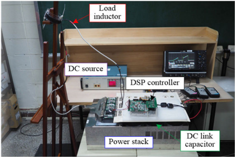
- Experimental verification used a DPT with digital oscilloscopes, 6 kA current probes, and a DSP-based control board; MRIC and MCD were compared between traditional and proposed POBs.
Limitations
- The paper states that no Spice model was available for the IGBT modules, so the high-side IGBT was assumed always off and the low-side IGBT was driven by an ideal gate driver in cosimulation.
- The paper states that the IGBT module simulation used a simplified flat copper bonding model rather than a multiple wire-bonding model, which likely explains why the measured static-path inductance (36.5 nH) exceeded the simulated value (30.3 nH).
- The paper states that DPT wiring of the load inductor affects current balancing and must be perpendicular to the POB and DC busbar; it also notes that proximity effect may have increased IGBT 2 impedance in the experiment. Evident from the scope, validation is limited to a single-phase power stack and static current sharing under DPT, not a full three-phase inverter or dynamic current sharing.
Model-written summary. Check it against the paper before relying on it.
Integrity signals
Registry
Cites
Statistics
Figures






Verification
Claims the paper makes
43 Own result · 15 Own interpretation · 7 Own method · 2 Not checked yet · 1 Sources not found · 1 No full text of the sources
A result the paper reports from its own data — it cites no other source for it, so there is none to check. The quote shows it is in the paper.
In the paper
“The simulated and experimental MRIC values of the proposed POB were 0.8% and 0.9%, respectively.”
- Also stated in: § V. CONCLUSION · plain
“The simulated and experimental MRIC values of the proposed POB were 0.8% and 0.9%, respectively.”
§ Simulation-Assisted Design of a Power Stack for Improving Static Current Sharing Among Three IGBT Modules Connected in Parallel > C. CURRENT SHARING TEST OF SINGLE POWER STACK
plain- Asserted: passes — The authors put it forward as true.
- Checkable: passes — It can be checked against evidence.
- Load-bearing: passes — The paper’s conclusions depend on it.
- Based: passes — The paper gives a reason why it holds.
- Also stated in: § V. CONCLUSION · plain
A result the paper reports from its own data — it cites no other source for it, so there is none to check. The quote shows it is in the paper.
In the paper
“The maximal error between the simulation and experimental results is less than 3.1%, which indicates a satisfactory match between the cosimulation and measurement results.”
§ Simulation-Assisted Design of a Power Stack for Improving Static Current Sharing Among Three IGBT Modules Connected in Parallel > B. VERIFICATION OF POB INDUCTANCE
plain- Asserted: passes — The authors put it forward as true.
- Checkable: passes — It can be checked against evidence.
- Load-bearing: passes — The paper’s conclusions depend on it.
- Based: passes — The paper gives a reason why it holds.
A result the paper states — it cites no source for it, so there is none to check. The quote shows it is in the paper.
In the paper
“simulation method were effective for achieving near-equal stray inductances among the three current flow paths.”
§ Simulation-Assisted Design of a Power Stack for Improving Static Current Sharing Among Three IGBT Modules Connected in Parallel > D. DC BUSBAR DESIGN
plainstates a cause- Asserted: passes — The authors put it forward as true.
- Checkable: passes — It can be checked against evidence.
- Load-bearing: passes — The paper’s conclusions depend on it.
- Based: passes — The paper gives a reason why it holds.
A result the paper reports from its own data — it cites no other source for it, so there is none to check. The quote shows it is in the paper.
In the paper
“Moreover, the maximum ratio of imbalanced current (MRIC) was 0.9% under a 200% (2400A) rated current of an IGBT module.”
§ Simulation-Assisted Design of a Power Stack for Improving Static Current Sharing Among Three IGBT Modules Connected in Parallel > I. INTRODUCTION
plain- Asserted: passes — The authors put it forward as true.
- Checkable: passes — It can be checked against evidence.
- Load-bearing: passes — The paper’s conclusions depend on it.
- Based: passes — The paper gives a reason why it holds.
A result the paper reports from its own data — it cites no other source for it, so there is none to check. The quote shows it is in the paper.
In the paper
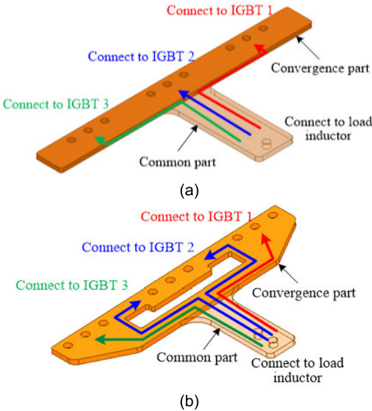
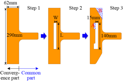
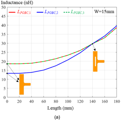
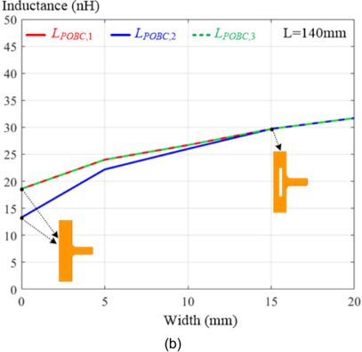
“Moreover, the stray inductance of the proposed convergence part along path 2 was marginally higher than those along paths 1 and 3 for compensating for the stray inductance in the DC busbar.”
§ Simulation-Assisted Design of a Power Stack for Improving Static Current Sharing Among Three IGBT Modules Connected in Parallel > 3) STEP3: FINE-TURN THE PROPOSED POB
plainstates a cause- Asserted: passes — The authors put it forward as true.
- Checkable: passes — It can be checked against evidence.
- Load-bearing: passes — The paper’s conclusions depend on it.
- Based: passes — The paper gives a reason why it holds.
44 more claims
Create a free account to see all 69 claims and to verify the 2 references still open.
- It may state two separate claims as one. 12
- Probably not a substantial claim. 10
- The quote only partly states this claim. 1
Citations
Cites
Prospects of multilevel VSC technologies for power transmission
Gemmell, B. D., Dorn, J., Retzmann, D., & Soerangr, D. (2008) · IEEE PES Transmission and Distribution Conference and Exhibition · doi:10.1109/tdc.2008.4517192 · Cited by 417
Characterization and Implementation of Dual-SiC MOSFET Modules for Future Use in Traction Converters
Fabre, J., Ladoux, P., & Piton, M. (2014) · IEEE Transactions on Power Electronics · doi:10.1109/tpel.2014.2352863 · Cited by 164
Bus Bar Design for High-Power Inverters
Callegaro, A. D., Guo, J., Eull, M., Danen, B., Gibson, J., Preindl, M., Bilgin, B., & Emadi, A. (2017) · IEEE Transactions on Power Electronics · doi:10.1109/tpel.2017.2691668 · Cited by 129
Bortis, D., Biela, J., & Kolar, J. W. (2008) · IEEE Transactions on Plasma Science · doi:10.1109/tps.2008.2003971 · Cited by 127
Mission Profile Based Reliability Evaluation of Capacitor Banks in Wind Power Converters
Zhou, D., Song, Y., Liu, Y., & Blaabjerg, F. (2018) · IEEE Transactions on Power Electronics · doi:10.1109/tpel.2018.2865710 · Cited by 87
Static and dynamic behavior of paralleled IGBTs
Letor, R. (1992) · IEEE Transactions on Industry Applications · doi:10.1109/28.126748 · Cited by 86
Reduced layer planar busbar for voltage source inverters
Zare, F., & Ledwich, G. F. (2002) · IEEE Transactions on Power Electronics · doi:10.1109/tpel.2002.800990 · Cited by 71
Comparison of 1700-V SiC-MOSFET and Si-IGBT Modules Under Identical Test Setup Conditions
Fuentes, C. D., Kouro, S., & Bernet, S. (2019) · IEEE Transactions on Industry Applications · doi:10.1109/tia.2019.2934713 · Cited by 52
Busbar design considerations for high power IGBT converters
Beukes, H. J., Enslin, J. H. R., & Spée, R. (2002) · IEEE Power Electronics Specialists Conference (PESC) · doi:10.1109/pesc.1997.616819 · Cited by 46
Barrera-Cárdenas, R., & Molinas, M. (2014) · IEEE Journal of Emerging and Selected Topics in Power Electronics · doi:10.1109/jestpe.2014.2360578 · Cited by 35
Research works printed but not linked: 16
- Tsuda, LV100 high voltage dual package in paralleling operation, 1
- Laska, New traction converter with low inductive high-voltage half bridge IGBT module, 1
- 2013, Fuji IGBT Modules for MV, SVG Inverter
- 2011, Parallel Connection
- 2013, Solutions for Wind Energy Systems
- 2021, Power Electronics for Wind Turbines
- 2014, Paralleling of IGBTs
- 2017, IGBT Modules in Parallel Operation With Central and Individual Driver Board
- 2010, HybridPACKTM Automotive Power Modules
- 2020, The Next Generation Standard Module for High Power: LV100 Optimized for Renewable and Industrial Applications
- 2020, CM1200DW-34T, Datasheet
- 2013, Paralleling of IGBT Modules
- 2004, Paralleling of EconoPACKTM
- Wissen, Effects of influencing the individual leg inductance in case of paralleling modules on basis of XHP 3 and EconoDUAL, 1
- 2017, Parallel Connection for PrimePACK
- Bayerer, Parasitic inductance hindering utilization of power devices, 1
Cited by
Zhang, J., Lei, E., Jin, L., Ma, K., Li, Y., Li, X., Xia, C., & Wang, X. (2023) · Energies · doi:10.3390/en16145306 · Cited by 6
Parametric compensation based dynamic current balancing strategy for parallel IGBTs
Peng, L., Huang, H., & Wang, H. (2025) · Journal of Power Electronics · doi:10.1007/s43236-024-00981-4 · Cited by 4
Liu, Y., Fu, P., Zhang, X., Huang, L., He, S., & Chen, X. (2024) · IEEE Transactions on Plasma Science · doi:10.1109/tps.2024.3354284 · Cited by 2
Static Current Balancing Strategy for Parallel IGBTs Based on Parametric Compensation
Peng, L., Huang, H., & Wang, H. (2024) · IEEE Transactions on Plasma Science · doi:10.1109/tps.2024.3446817 · Cited by 2
Gate Driver Design and Device Characterization for 3.3 kV SiC MOSFET Modules
Gutierrez, B., Hou, Z., Jiao, D., Hsieh, H.-C., Chen, X.-R., Liao, H., Lai, J., Yu, M.-H., & Chen, K. (2023) · IEEE Energy Conversion Congress and Exposition (ECCE) · doi:10.1109/ecce53617.2023.10362206 · Cited by 1
Metadata
- Authors
- Li, Z.-F., Nishida, N., Aoki, H., Shibata, H., Liao, C.-C., & Huang, M.-S.
- Affiliations
- National Taipei University of Technology (TW)
- Mitsubishi Electric (Japan) (JP)
- Tamura Corporation (Japan) (JP)
- Venue
- IEEE Access
- Published
- 2022
- Volume
- 10
- Pages
- 10079-10093
- ISSN
- 2169-3536 (ISSN-L)
- OpenAlex
- W4206346422
- Semantic Scholar
- ed0ce8e9a50ccad56a14e93ba10bda3b8d528030
- Cited by
- 9
- References
- 29
- Citations by year
- 2026: 1 · 2025: 3 · 2024: 3 · 2023: 2
- FWCI
- 0.55
- Type
- journal article
- Language
- en
- Open access
- gold
- doi.org
- Locations
- IEEE Access (publishedVersion, cc-by)
- DOAJ (DOAJ: Directory of Open Access Journals) (submittedVersion, cc-by-sa)
- Funders
- TAMURA Corporation (208Q12)
- Topics
- Physical Sciences › Engineering › Electrical and Electronic Engineering › Silicon Carbide Semiconductor Technologies
- Physical Sciences › Engineering › Electrical and Electronic Engineering › Multilevel Inverters and Converters
- Physical Sciences › Engineering › Electrical and Electronic Engineering › Advanced DC-DC Converters
- Keywords
- IGBT modules, current sharing, parasitic inductance, co-simulation, Simplorer, double pulse test, power density, high power applications
About these checks
Registry, retraction, Cites and statistics results are computed, not judged, with one exception: a printed reference that no index lists is read once by a model before it counts as a citation error. Claims are extracted by a model and kept only when their quote appears verbatim in the text; each cited source is then checked, with a model’s help, for whether it says what the claim relies on. Those verdicts can be wrong — read the claim’s quote and the cited source before relying on one.
A language model drew the claims from the paper on 2026-11-12, under version 3 of the claim definition (model deepseek-v4.1-flash, prompt extract-v3).
A second model labelled each claim on 2026-11-12 (model jev-1.13-20260917, definition revision gold-guideline-v0.2).
Statistics and arithmetic are recomputed, not judged.
Confidence bands are shown only for fields calibrated on our annotated test set. None is calibrated yet, so no band is shown.
What counts as a claim ›How we measure confidence ›How we check this ›
Are you an author, or do you see a problem with this page? Request a review
Data sources
Bibliographic data: Semantic Scholar, OpenAlex, Crossref.
Contains information from the Semantic Scholar Academic Graph Datasets, made available under the ODC Attribution License (ODC-BY 1.0).
Semantic Scholar’s data is described in: Kinney, R., et al. (2023). The Semantic Scholar Open Data Platform. arXiv:2301.10140.
