

The DOI matches its Crossref record; 77 of the 77 references it cites were found in a registry or an index.
Oriented assembly of anisotropic nanoparticles into frame-like superstructures
Open accessAbstract
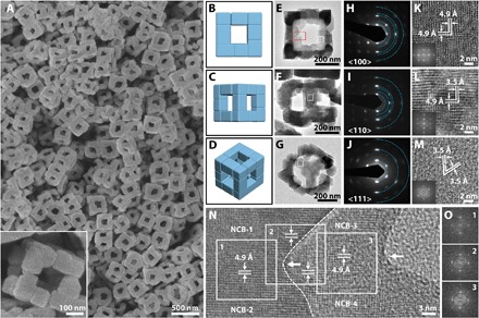
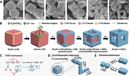
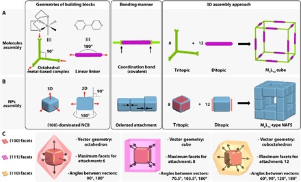
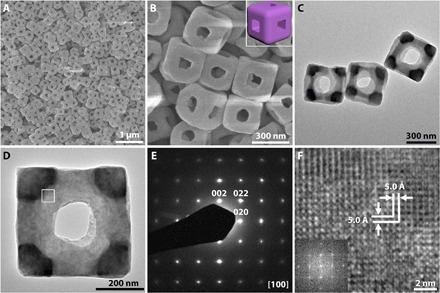
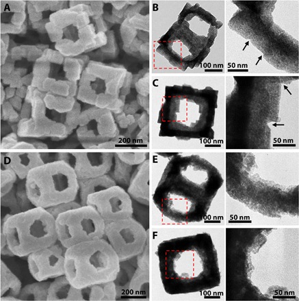
Cubic frame–like superstructures are constructed via the assembly of nanocuboids on the edges of preformed nanocubes.
Overview
The claims and statistics of this paper haven’t been checked yet.
Run the check — free, no account needed. It reads the open-access text and checks the sources it cites.
Integrity signals
Registry
Cites
Statistics
Figures
Verification
Claims the paper makes
The claims and statistics of this paper haven’t been checked yet.
Run the check — free, no account needed. It reads the open-access text and checks the sources it cites.
Claims other papers make about this one
Each is checked against this paper’s own text: does it say what the citing paper says it does?
The cited source says what the claim attributes to it.
In the citing paper
“the main phase corresponding to diffraction patterns labelling with A-(200), A-(220) and A-(400) is attributed to the face and the body of the CoFe-PBA nanocube (pink in Fig. 1a). The other phase labelling with B-(200), B-(220) and B-(400) which has a slight up-shift diffraction patterns is assigned to the edge of the CoFe-PBA nanocube (blue in Fig. 1a) [36].”
From Encapsulating hollow (Co,Fe)P nanoframes into N,P-codoped graphene aerogel for highly efficient water splitting (2020) · cites this paper as [36]
Self-check
Percentages, sums and reported differences re-computed from the paper’s own numbers.
The self-check needs the paper’s full text.
Citations
Cites
Co3O4 nanocrystals on graphene as a synergistic catalyst for oxygen reduction reaction
Liang, Y., Li, Y., Wang, H., Zhou, J., Wang, J., Regier, T., & Dai, H. (2011) · Nature Materials · doi:10.1038/nmat3087 · Cited by 5,518
Supramolecular Coordination: Self-Assembly of Finite Two- and Three-Dimensional Ensembles
Chakrabarty, R., Mukherjee, P. S., & Stang, P. J. (2011) · Chemical Reviews · doi:10.1021/cr200077m · Cited by 2,963
Cook, T. R., Zheng, Y., & Stang, P. J. (2012) · Chemical Reviews · doi:10.1021/cr3002824 · Cited by 2,960
Anisotropy of building blocks and their assembly into complex structures
Glotzer, S. C., & Solomon, M. J. (2007) · Nature Materials · doi:10.1038/nmat1949 · Cited by 2,797
Proton-Coupled Electron Transfer
Weinberg, D. R., Gagliardi, C. J., Hull, J. F., Murphy, C. F., Kent, C. A., Westlake, B. C., Paul, A., Ess, D. H., McCafferty, D. G., & Meyer, T. J. (2012) · Chemical Reviews · doi:10.1021/cr200177j · Cited by 2,462
Structural diversity in binary nanoparticle superlattices
Shevchenko, E. V., Talapin, D. V., Kotov, N. A., O'Brien, S. P., & Murray, C. B. (2006) · Nature · doi:10.1038/nature04414 · Cited by 2,147
Spontaneous Organization of Single CdTe Nanoparticles into Luminescent Nanowires
Tang, Z., Kotov, N. A., & Giersig, M. (2002) · Science · doi:10.1126/science.1072086 · Cited by 1,824
Photoinduced Magnetization of a Cobalt-Iron Cyanide
Sato, O., Iyoda, T., Fujishima, A., & Hashimoto, K. (1996) · Science · doi:10.1126/science.272.5262.704 · Cited by 1,803
Properties and emerging applications of self-assembled structures made from inorganic nanoparticles
Nie, Z., Petukhova, A., & Kumacheva, E. (2009) · Nature Nanotechnology · doi:10.1038/nnano.2009.453 · Cited by 1,598
Solution-Cast Metal Oxide Thin Film Electrocatalysts for Oxygen Evolution
Trotochaud, L., Ranney, J. K., Williams, K. N., & Boettcher, S. W. (2012) · Journal of the American Chemical Society · doi:10.1021/ja307507a · Cited by 1,565
Cited by
Sorted by citations
Items 201–203 of 203
Ren, X., Meng, Z., Guan, L., Wang, Y., Chen, Z., Li, Z., Lian, H., & Mu, Y. (2026) · Exploration · doi:10.1002/exp2.70209
Synthesis, Self-Assembly, Graph Theory, and Applications of Complex Nanoparticle Systems
Crockett, J. R., Li, J., Kim, C., Xiao, X., Veksler, M., Wang, Z., Akter, R., Hwang, C.-Y., Wang, X., Mao, X., et al. (2026) · Chemical Reviews · doi:10.1021/acs.chemrev.5c00965
Kong, L., Yan, B., Nan, J., Qiao, J., Xia, L., Zhang, S., Ruan, Q., & Sun, Z. (2026) · Nano Energy · doi:10.1016/j.nanoen.2026.112422
Metadata
- Authors
- Nai, J., Guan, B. Y., Yu, L., & Lou, X. W. (.
- Affiliations
- Nanyang Technological University (SG)
- Corresponding author
- Lou, Xiong Wen (David)
- Venue
- Science Advances
- Published
- 2017-08-04
- Volume
- 3
- Issue
- 8
- Pages
- e1700732-e1700732
- ISSN
- 2375-2548 (ISSN-L)
- PMC
- PMC5567758
- OpenAlex
- W2747678498
- Cited by
- 206
- References
- 77
- Citations by year
- 2026: 7 · 2025: 17 · 2024: 21 · 2023: 33 · 2022: 24 · 2021: 28 · 2020: 16 · 2019: 30 · 2018: 26 · 2017: 4
- FWCI
- 7.49
- Type
- journal article
- Language
- en
- Open access
- gold
- doi.org
- Licence
- cc-by-nc
- Locations
- Science Advances (publishedVersion, cc-by-nc)
- Europe PMC (PubMed Central) (publishedVersion, cc-by-nc)
- PubMed Central (publishedVersion, cc-by-nc)
- PubMed (publishedVersion)
- DR-NTU (Nanyang Technological University) (submittedVersion, cc-by-nc)
- Funders
- National Research Foundation of Singapore (award336770, NRF-NRFI2016-04)
- Topics
- Physical Sciences › Materials Science › Biomaterials › Supramolecular Self-Assembly in Materials
- Physical Sciences › Materials Science › Biomaterials › Calcium Carbonate Crystallization and Inhibition
- Physical Sciences › Chemistry › Organic Chemistry › Supramolecular Chemistry and Complexes
- Keywords
- oriented assembly, anisotropic nanoparticles, nanoparticle morphology, annealing, electrocatalysts, bottom-up assembly, directional bonding
About these checks
Registry, retraction, Cites and statistics results are computed, not judged, with one exception: a printed reference that no index lists is read once by a model before it counts as a citation error. Claims are extracted by a model and kept only when their quote appears verbatim in the text; each cited source is then checked, with a model’s help, for whether it says what the claim relies on. Those verdicts can be wrong — read the claim’s quote and the cited source before relying on one.
Statistics and arithmetic are recomputed, not judged.
Confidence bands are shown only for fields calibrated on our annotated test set. None is calibrated yet, so no band is shown.
What counts as a claim ›How we measure confidence ›How we check this ›
Are you an author, or do you see a problem with this page? Request a review
