

The DOI matches its Crossref record.
Experimental Parametric Relationships for Chip Geometry in Dry Machining of the Ti6Al4V Alloy
Open accessAbstract
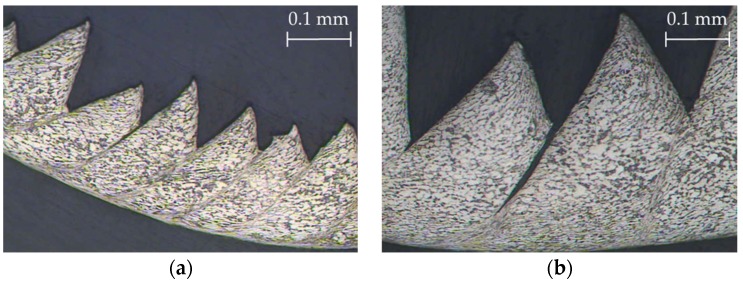
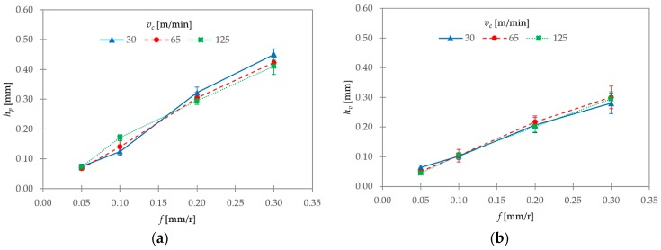
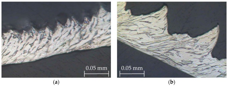
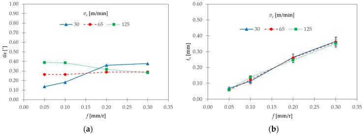
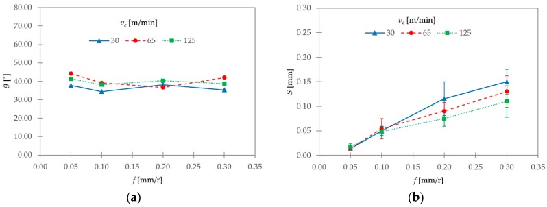
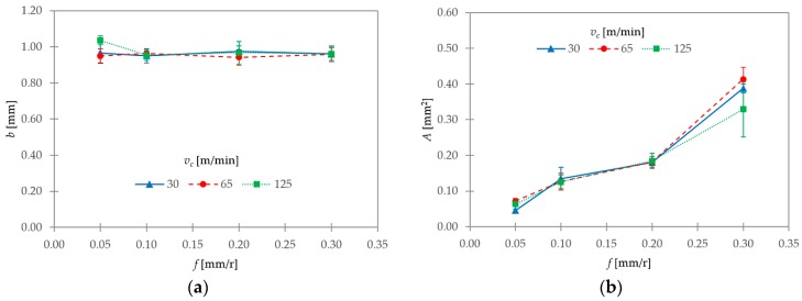
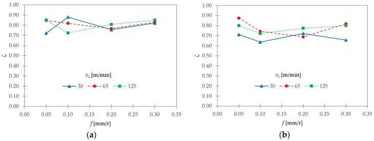
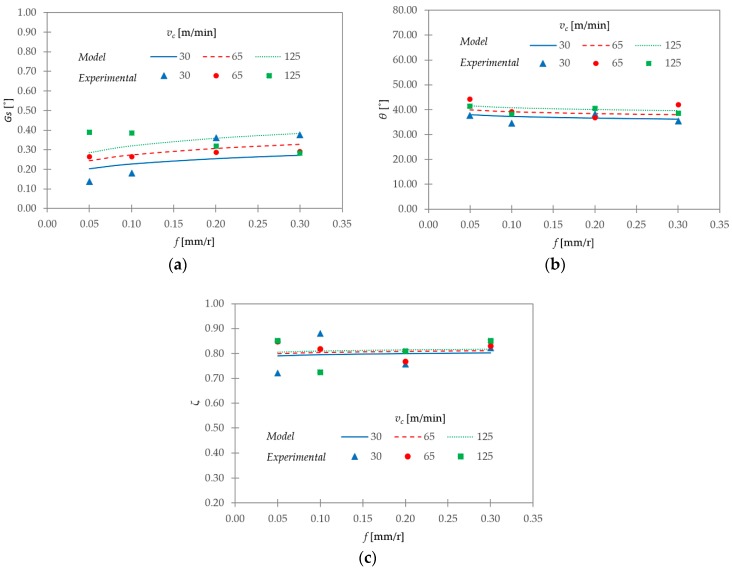
The Ti6Al4V alloy is included in the group of difficult-to-cut materials. Segmented chips are generated for a wide range of cutting parameters. This kind of chip geometry leads to the periodic variation of machining forces, tool vibrations, and work part-tolerance inaccuracies. Therefore, the analysis of chip morphology and geometry becomes a fundamental machinability criterion. However, few studies propose experimental parametric relationships that allow predicting chip-geometry evolution as a function of cutting parameters. In this work, an experimental analysis of the influence of cutting speed and feed rate on various chip-geometric parameters in dry machining of the Ti6Al4V alloy was carried out. In addition, the chip morphology and chip microstructure were studied. A clear dependence of certain chip-geometric parameters on the cutting parameters studied was found. From the experimental data, several parametric relationships were developed. These relationships were able to predict the evolution of different geometric parameters as a function of cutting speed and feed, within the tested range of values. The differences between the proposed models and the experimental data were also highlighted. These parametric equations allowed quantifying the value of parameters in which the trend was clear.
Overview
The claims and statistics of this paper haven’t been checked yet.
Run the check — free, no account needed. It reads the open-access text and checks the sources it cites.
Integrity signals
Registry
Cites
Statistics
Figures
Verification
Claims the paper makes
The claims and statistics of this paper haven’t been checked yet.
Run the check — free, no account needed. It reads the open-access text and checks the sources it cites.
Claims other papers make about this one
Each is checked against this paper’s own text: does it say what the citing paper says it does?
The source backs part of the claim, not all of it — or backs it for a different population, condition or comparison.
In the citing paper
“Machining of Titanium alloys produces serrated chips due to shear deformation and results in a saw-tooth like structure as already reported [33, 36].”
From Machinability Performance of Single Coated and Multicoated Carbide Tools During Turning Ti6Al4V Alloy (2025) · cites this paper as [36]
Experimental — accuracy not yet measuredThe source backs part of the claim, not all of it — or backs it for a different population, condition or comparison.
In the citing paper
“The trend is increasing because of the linear proportionality of chip thickness and segmented ratio respectively, with respect to cutting speeds as also reported elsewhere [33, 36].”
From Machinability Performance of Single Coated and Multicoated Carbide Tools During Turning Ti6Al4V Alloy (2025) · cites this paper as [36]
Experimental — accuracy not yet measuredThe source backs part of the claim, not all of it — or backs it for a different population, condition or comparison.
In the citing paper
“Titanium based alloy form shear deformed chips even at lower speeds, as a result the conventional trend of decreasing chip thickness with increasing speed, which is well known for conventional alloys, is not the case for titanium based alloys.”
From Machinability Performance of Single Coated and Multicoated Carbide Tools During Turning Ti6Al4V Alloy (2025) · cites this paper as [36]
Experimental — accuracy not yet measuredThe cited source says what the claim attributes to it.
In the citing paper
“It was reported that cutting speed influences the segmented portion of chip structure as higher cutting speeds attributes to the thermal softening during cutting titanium alloy [36, 40].”
From Machinability Performance of Single Coated and Multicoated Carbide Tools During Turning Ti6Al4V Alloy (2025) · cites this paper as [36]
The cited source says what the claim attributes to it.
In the citing paper
“Titanium based alloy form shear deformed chips even at lower speeds, as a result the conventional trend of decreasing chip thickness with increasing speed, which is well known for conventional alloys, is not the case for titanium based alloys.”
From Machinability Performance of Single Coated and Multicoated Carbide Tools During Turning Ti6Al4V Alloy (2025) · cites this paper as [36]
The check wasn’t confident either way, so it gives no verdict — never disputed.
In the citing paper
“As the cutting angle and the radius of the cutting edge is increased, the chip compression ratio increases [13, 36].”
From Machinability Performance of Single Coated and Multicoated Carbide Tools During Turning Ti6Al4V Alloy (2025) · cites this paper as [36]
Experimental — accuracy not yet measured
Self-check
Percentages, sums and reported differences re-computed from the paper’s own numbers.
The self-check needs the paper’s full text.
Citations
Cites
Still being checked.
Research works printed but not linked: 46
- Ezugwu, 2003, An overview of the machinability of aeroengine alloys, J. Mater. Process. Technol., 134, 233, 10.1016/S0924-0136(02)01042-7 · DOI
- Niknam, S.A., Khettabi, R., and Songmene, V. (2014). Machinability and Machining of Titanium Alloys: A Review. Machining of Titanium Alloys, Springer. Chapter 1. · DOI
- Veiga, 2013, Review on machinability of titanium alloys: The process perspective, Rev. Adv. Mater. Sci., 34, 148
- Arrazola, 2009, Machinability of titanium alloys (Ti6Al4V and Ti555.3), J. Mater. Process. Technol., 209, 2223, 10.1016/j.jmatprotec.2008.06.020 · DOI
- Llorente, 2000, Advanced cutting conditions for the milling of aeronautical alloys, J. Mater. Process. Technol., 100, 1, 10.1016/S0924-0136(99)00372-6 · DOI
- Boyer, 2013, The use of β titanium alloys in the aerospace industry, J. Mater. Eng. Perform., 22, 2916, 10.1007/s11665-013-0728-3 · DOI
- Li, 2017, Mechanical behaviors of Ti/CFRP/Ti laminates with different surface treatments of titanium sheets, Compos. Struct., 163, 21, 10.1016/j.compstruct.2016.12.033 · DOI
- Calamaz, 2009, A new material model for 2D numerical simulation of serrated chip formation when machining titanium alloy Ti-6Al-4V, Int. J. Mach. Tools Manuf., 48, 275, 10.1016/j.ijmachtools.2007.10.014 · DOI
- Nouari, M., and Makich, H. (2014). Analysis of Physical Cutting Mechanisms and Their Effects on the Tool Wear and Chip Formation Process When Machining Aeronautical Titanium Alloys: Ti-6Al-4V and Ti-55531. Machining of Titanium Alloys, Springer. · DOI
- Nouari, 2014, On the Physics of Machining Titanium Alloys: Interactions between Cutting Parameters, Microstructure and Tool Wear, Metals, 4, 335, 10.3390/met4030335 · DOI
- Cotterell, 2008, Dynamics of chip formation during orthogonal cutting of titanium alloy Ti-6Al-4V, CIRP Ann. Manuf. Technol., 57, 93, 10.1016/j.cirp.2008.03.007 · DOI
- Pramanik, 2014, Problems and solutions in machining of titanium alloys, Int. J. Adv. Manuf. Technol., 70, 919, 10.1007/s00170-013-5326-x · DOI
- Komanduri, 2002, On thermoplastic shear instability in the machining of a titanium alloy (Ti-6Al-4V), Metall. Mater. Trans. A, 33, 2995, 10.1007/s11661-002-0284-1 · DOI
- Wan, 2012, Microstructure evolution of adiabatic shear bands and mechanisms of saw-tooth chip formation in machining Ti6Al4V, Mater. Sci. Eng. A, 531, 155, 10.1016/j.msea.2011.10.050 · DOI
- Sima, 2010, Modified material constitutive models for serrated chip formation simulations and experimental validation in machining of titanium alloy Ti-6Al-4V, Int. J. Mach. Tools Manuf., 50, 943, 10.1016/j.ijmachtools.2010.08.004 · DOI
- Shokrani, 2012, Environmentally conscious machining of difficult-to-machine materials with regard to cutting fluids, Int. J. Mach. Tools Manuf., 57, 83, 10.1016/j.ijmachtools.2012.02.002 · DOI
- Kelly, 2002, Minimal lubrication machining of aluminium alloys, J. Mater. Process. Technol., 120, 327, 10.1016/S0924-0136(01)01126-8 · DOI
- Yoshimura, 2006, Study on near dry cutting of aluminum alloys, Mach. Sci. Technol., 10, 289, 10.1080/10910340600902108 · DOI
- Vinayagamoorthy, 2013, Dry machining of Ti-6Al-4V using PVD coated tools, Int. J. Appl. Eng. Res., 8, 1373
- Salguero, 2012, A Study of Macrogeometrical Deviations in the Dry Turning of UNS R56400 Ti Alloy, Appl. Mech. Mater., 152–154, 613, 10.4028/www.scientific.net/AMM.152-154.613 · DOI
- Ginting, 2009, Surface integrity of dry machined titanium alloys, Int. J. Mach. Tools Manuf., 49, 325, 10.1016/j.ijmachtools.2008.10.011 · DOI
- Trujillo, F.J., Sevilla, L., and Marcos, M. (2017). Experimental Parametric Model for Indirect Adhesion Wear Measurement in the Dry Turning of UNS A97075 (Al-Zn) Alloy. Materials, 10. · DOI
- Hua, 2004, Prediction of chip morphology and segmentation during the machining of titanium alloys, J. Mater. Process. Technol., 150, 124, 10.1016/j.jmatprotec.2004.01.028 · DOI · Paper page
- Molinari, 2013, Adiabatic shear banding and scaling laws in chip formation with application to cutting of Ti–6Al–4V, J. Mech. Phys. Solids, 61, 2331, 10.1016/j.jmps.2013.05.006 · DOI
- Liang, 2010, Experimental Studies for Burrs in Dry Drilling of Stacked Metal Materials, Adv. Mater. Res., 129–131, 959, 10.4028/www.scientific.net/AMR.129-131.959 · DOI
- Yang, 1999, Machining Titanium and its Alloys, Mach. Sci. Technol., 3, 107, 10.1080/10940349908945686 · DOI
- Calamaz, 2010, Numerical simulation of titanium alloy dry machining with a strain softening constitutive law, Mach. Sci. Technol., 14, 244, 10.1080/10910344.2010.500957 · DOI
- Yameogo, 2017, Prediction of the Cutting Forces and Chip Morphology When Machining the Ti6Al4V Alloy Using a Microstructural Coupled Model, Procedia CIRP, 58, 335, 10.1016/j.procir.2017.03.233 · DOI
- Vyas, 1999, Mechanics of saw-tooth chip formation in metal cutting, J. Manuf. Sci. Eng., 121, 163, 10.1115/1.2831200 · DOI
- Barry, 2001, Observations on chip formation and acoustic emission in machining Ti-6Al-4V alloy, Int. J. Mach. Tools Manuf., 41, 1055, 10.1016/S0890-6955(00)00096-1 · DOI
- Komanduri, 1981, New observations on the mechanism of chip formation when machining titanium alloys, Wear, 69, 179, 10.1016/0043-1648(81)90242-8 · DOI · Paper page
- Obikawa, 1996, Computational machining of titanium alloy—Finite element modeling and a few results, J. Manuf. Sci. Eng. Trans. ASME, 118, 208, 10.1115/1.2831013 · DOI
- Bai, 2017, Improved analytical prediction of chip formation in orthogonal cutting of titanium alloy Ti6Al4V, Int. J. Mech. Sci., 133, 357, 10.1016/j.ijmecsci.2017.08.054 · DOI
- Joshi, 2018, Dimensional inequalities in chip segments of titanium alloys, Eng. Sci. Technol. Int. J., 21, 238
- Turley, 1982, Calculation of shear strains in chip formation in titanium, Mater. Sci. Eng., 55, 45, 10.1016/0025-5416(82)90082-9 · DOI
- Sutter, 2013, Very high speed cutting of Ti-6Al-4V titanium alloy—Change in morphology and mechanism of chip formation, Int. J. Mach. Tools Manuf., 66, 37, 10.1016/j.ijmachtools.2012.11.004 · DOI
- Joshi, 2015, Microstructural Characterization of Chip Segmentation under Different Machining Environments in Orthogonal Machining of Ti6Al4V, J. Eng. Mater. Technol., 137, 011055, 10.1115/1.4028841 · DOI
- Baker, 2002, Finite Element Simulation of Segmented Chip Formation of Ti6Al4V, J. Manuf. Sci. Eng., 124, 485, 10.1115/1.1459469 · DOI
- Zhang, 2015, On the selection of Johnson-Cook constitutive model parameters for Ti-6Al-4V using three types of numerical models of orthogonal cutting, Procedia CIRP, 31, 112, 10.1016/j.procir.2015.03.052 · DOI
- Wang, 2015, Shear localization sensitivity analysis for Johnson-Cook constitutive parameters on serrated chips in high speed machining of Ti6Al4V, Simul. Model. Pract. Theory, 55, 63, 10.1016/j.simpat.2015.03.011 · DOI
- Ducobu, 2016, Material constitutive model and chip separation criterion influence on the modeling of Ti6Al4V machining with experimental validation in strictly orthogonal cutting condition, Int. J. Mech. Sci., 107, 136, 10.1016/j.ijmecsci.2016.01.008 · DOI
- Batista, 2012, Using image analysis techniques for single evaluation of the chip shrinkage factor in orthogonal cutting process, Key Eng. Mater., 504–506, 1329, 10.4028/www.scientific.net/KEM.504-506.1329 · DOI
- Dye, D., Hu, F., and Jones, N.G. (2011). Microstructure Formation in Alpha-Beta Titanium Alloys. Titanium, Springer.
- Lütjering, G., and Williams, J.C. (2007). Alpha + Beta Alloys. Titanium, Springer.
- Molinari, 2002, Adiabatic shear banding in high speed machining of Ti-6Al-4V: Experiments and modeling, Int. J. Plast., 18, 443, 10.1016/S0749-6419(01)00003-1 · DOI
- Grzesik, W. (2008). Advanced Machining Processes of Metallic Materials: Theory, Modelling and Applications, Elsevier.
Cited by
Sorted by citations
Ali, A., Younas, M., Khan, M., Jaffery, S. H. I., & Khan, Z. (2025) · International Journal of Precision Engineering and Manufacturing · doi:10.1007/s12541-024-01147-9 · Cited by 31
Hassan, A., Khan, M. A., Younas, M., Jaffery, S. H. I., Khan, M., Ahmed, N., & Awang, M. (2024) · International Journal of Automotive and Mechanical Engineering · doi:10.15282/ijame.21.2.2024.11.0874 · Cited by 4
Metadata
- Authors
- Sánchez Hernández, Y., Trujillo Vilches, F. J., Bermudo Gamboa, C., & Sevilla Hurtado, L.
- Affiliations
- Department of Manufacturing Engineering, EII, Universidad de Málaga, E-29071 Málaga, Spain
- Venue
- Materials
- Publisher
- MDPI AG
- Published
- 2018-07-23
- Volume
- 11
- Issue
- 7
- Pages
- 1260
- ISSN
- 1996-1944 (ISSN-L)
- PMC
- PMC6073982
- OpenAlex
- W2884431689
- Cited by
- 36
- References
- 0
- Citations by year
- 2026: 1 · 2025: 3 · 2024: 8 · 2023: 4 · 2022: 5 · 2021: 4 · 2020: 6 · 2019: 4 · 2018: 1
- FWCI
- 2.40
- Type
- journal article
- Language
- en
- Open access
- gold
- dx.doi.org
- Licence
- Locations
- Materials (publishedVersion, cc-by)
- Europe PMC (PubMed Central) (publishedVersion, cc-by)
- PubMed Central (publishedVersion, cc-by)
- PubMed (publishedVersion)
- DOAJ (DOAJ: Directory of Open Access Journals) (submittedVersion, cc-by-sa)
- Topics
- Physical Sciences › Engineering › Mechanical Engineering › Advanced machining processes and optimization
- Physical Sciences › Engineering › Industrial and Manufacturing Engineering › Advanced Machining and Optimization Techniques
- Physical Sciences › Engineering › Industrial and Manufacturing Engineering › Engineering Technology and Methodologies
- Keywords
- Ti-6Al-4V, titanium alloys, dry machining, chip geometry, chip morphology, segmented chips, cutting speed, feed rate, parametric relationships, chip microstructure, machinability, difficult-to-cut materials
About these checks
Registry, retraction, Cites and statistics results are computed, not judged, with one exception: a printed reference that no index lists is read once by a model before it counts as a citation error. Claims are extracted by a model and kept only when their quote appears verbatim in the text; each cited source is then checked, with a model’s help, for whether it says what the claim relies on. Those verdicts can be wrong — read the claim’s quote and the cited source before relying on one.
Statistics and arithmetic are recomputed, not judged.
Confidence bands are shown only for fields calibrated on our annotated test set. None is calibrated yet, so no band is shown.
What counts as a claim ›How we measure confidence ›How we check this ›
Are you an author, or do you see a problem with this page? Request a review
