

Single microwave-photon detector using an artificial Λ-type three-level system
Open accessThe DOI matches its Crossref record; 35 of the 35 references it cites were found in a registry or an index.
Abstract
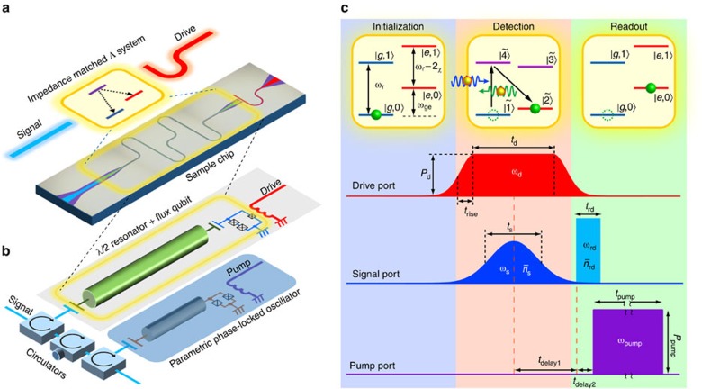
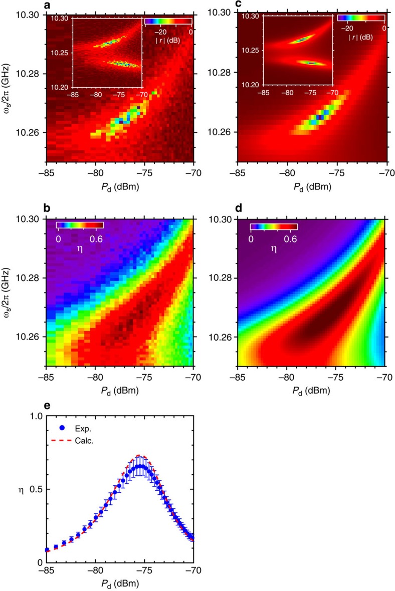
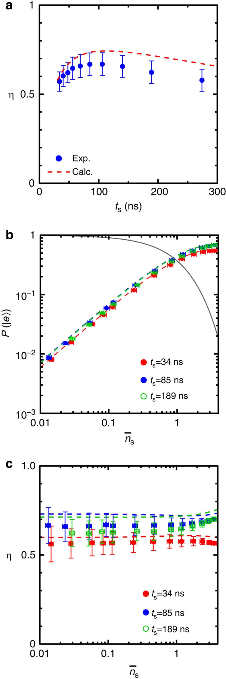
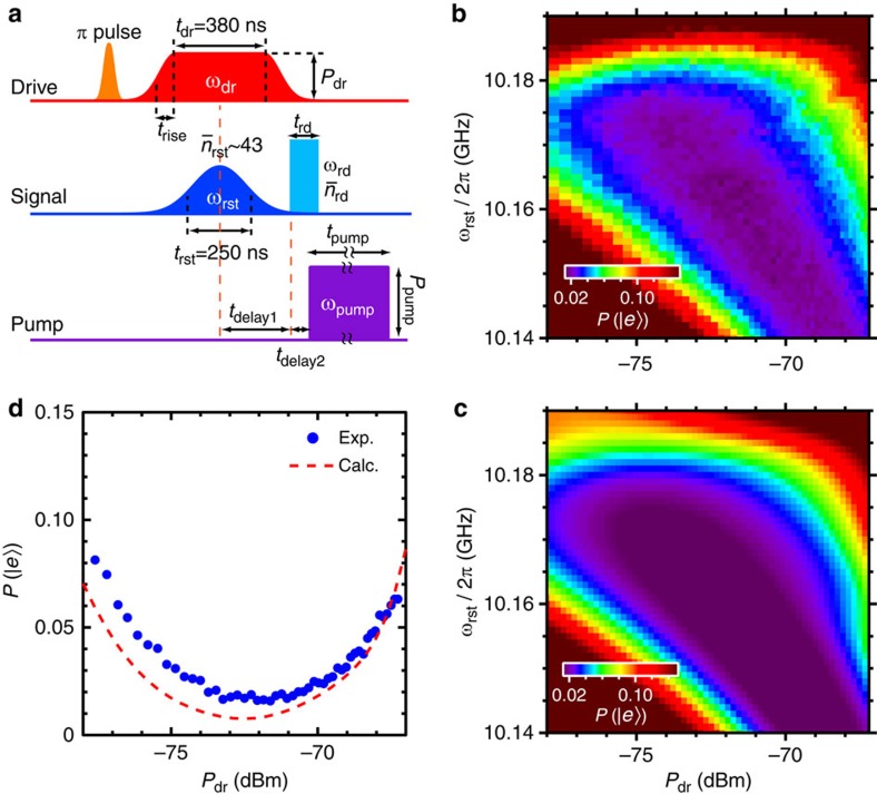
Single-photon detection is a requisite technique in quantum-optics experiments in both the optical and the microwave domains. However, the energy of microwave quanta are four to five orders of magnitude less than their optical counterpart, making the efficient detection of single microwave photons extremely challenging. Here we demonstrate the detection of a single microwave photon propagating through a waveguide. The detector is implemented with an impedance-matched artificial Λ system comprising the dressed states of a driven superconducting qubit coupled to a microwave resonator. Each signal photon deterministically induces a Raman transition in the Λ system and excites the qubit. The subsequent dispersive readout of the qubit produces a discrete ‘click’. We attain a high single-photon-detection efficiency of 0.66±0.06 with a low dark-count probability of 0.014±0.001 and a reset time of ∼400 ns. This detector can be exploited for various applications in quantum sensing, quantum communication and quantum information processing.
Overview
The claims and statistics of this paper haven’t been checked yet.
Free: it reads the open-access text and checks the first 5 claims that cite a source we can check. Create a free account to check every claim.
Integrity signals
Registry
Cites
Statistics
Figures
Verification
Claims the paper makes
The claims and statistics of this paper haven’t been checked yet.
Free: it reads the open-access text and checks the first 5 claims that cite a source we can check. Create a free account to check every claim.
Claims other papers make about this one
Each is checked against this paper’s own text: does it say what the citing paper says it does?
The cited source doesn’t support the claim as written.
In the citing paper
“In those cases, only MW fields consisting of one (and only one) photon can be observed, and these are irreversibly lost after the detection.”
From Coherent coupling of a trapped electron to a distant superconducting microwave cavity (2020) · cites this paper as [13]
Checked by a reasoning model — may be wrong.
Experimental — accuracy not yet measuredThe cited source says what the claim attributes to it.
In the citing paper
“This makes the electron a linear and reversible quantum microwave transducer, unlike single MW photon counters based upon three-level systems 12,13 and similar technologies.”
From Coherent coupling of a trapped electron to a distant superconducting microwave cavity (2020) · cites this paper as [13]
Self-check
Percentages, sums and reported differences re-computed from the paper’s own numbers.
The self-check needs the paper’s full text.
Citations
Cites
Gisin, N., Ribordy, G., Tittel, W., & Zbinden, H. (2002) · Reviews of Modern Physics · doi:10.1103/revmodphys.74.145 · Cited by 8,515
A scheme for efficient quantum computation with linear optics
Knill, E., Laflamme, R., & Milburn, G. J. (2001) · Nature · doi:10.1038/35051009 · Cited by 5,880
Single-photon detectors for optical quantum information applications
Hadfield, R. H. (2009) · Nature Photonics · doi:10.1038/nphoton.2009.230 · Cited by 1,726
Invited Review Article: Single-photon sources and detectors
Eisaman, M. D., Fan, J., Migdall, A., & Polyakov, S. V. (2011) · Review of Scientific Instruments · doi:10.1063/1.3610677 · Cited by 1,358
A single-photon transistor using nanoscale surface plasmons
Chang, D. E., Sørensen, A. S., Demler, E. A., & Lukin, M. D. (2007) · Nature Physics · doi:10.1038/nphys708 · Cited by 1,263
O'Brien, J. L. (2007) · Science · doi:10.1126/science.1142892 · Cited by 1,221
Scalable Photonic Quantum Computation through Cavity-Assisted Interactions
Duan, L.-M., & Kimble, H. J. (2004) · Physical Review Letters · doi:10.1103/physrevlett.92.127902 · Cited by 881
A near–quantum-limited Josephson traveling-wave parametric amplifier
Macklin, C., O’Brien, K., Hover, D., Schwartz, M. E., Bolkhovsky, V., Zhang, X., Oliver, W. D., & Siddiqi, I. (2015) · Science · doi:10.1126/science.aaa8525 · Cited by 821
Self-citationResonance Fluorescence of a Single Artificial Atom
Astafiev, O., Zagoskin, A. M., Abdumalikov, A. A., Pashkin, Y. A., Yamamoto, T., Inomata, K., Nakamura, Y., & Tsai, J. S. (2010) · Science · doi:10.1126/science.1181918 · Cited by 693
Self-citationPhoton-Mediated Interactions Between Distant Artificial Atoms
van Loo, A. F., Fedorov, A., Lalumière, K., Sanders, B. C., Blais, A., & Wallraff, A. (2013) · Science · doi:10.1126/science.1244324 · Cited by 533
Cited by
A quantum engineer's guide to superconducting qubits
Krantz, P., Kjaergaard, M., Yan, F., Orlando, T. P., Gustavsson, S., & Oliver, W. D. (2019) · Applied Physics Reviews · doi:10.1063/1.5089550 · Cited by 2,004
Self-citationCircuit quantum electrodynamics
Blais, A., Grimsmo, A. L., Girvin, S. M., & Wallraff, A. (2021) · Reviews of Modern Physics · doi:10.1103/revmodphys.93.025005 · Cited by 1,931
“Despite these challenges, first itinerant microwave photon detectors have been achieved in the laboratory (Chen et al., 2011; Inomata et al., 2016; Narla et al., 2016; Oelsner et al., 2017), in some cases achieving photon detection without destroying the photon in the process (Besse et al., 2018;…”
BackgroundMicrowave photonics with superconducting quantum circuits
Gu, X., Kockum, A. F., Miranowicz, A., Liu, Y.-X., & Nori, F. (2017) · Physics Reports · doi:10.1016/j.physrep.2017.10.002 · Cited by 1,307
“[340, 341, 506], a flux qubit placed in a resonator realized an effective three-level Λ system [see Fig.”
Hybrid quantum systems based on magnonics
Lachance-Quirion, D., Tabuchi, Y., Gloppe, A., Usami, K., & Nakamura, Y. (2019) · Applied Physics Express · doi:10.7567/1882-0786/ab248d · Cited by 752
Self-citationPhotonic quantum information processing: a review
Flamini, F., Spagnolo, N., & Sciarrino, F. (2019) · Reports on Progress in Physics · doi:10.1088/1361-6633/aad5b2 · Cited by 770
Metadata
- Authors
- Inomata, K., Lin, Z., Koshino, K., Oliver, W. D., Tsai, J.-S., Yamamoto, T., & Nakamura, Y.
- Affiliations
- RIKEN Center for Emergent Matter Science (JP)
- Tokyo Medical and Dental University (JP)
- MIT Lincoln Laboratory (US)
- Tokyo University of Science (JP)
- NEC (Japan) (JP)
- Corresponding author
- Inomata, Kunihiro
- ORCID
- Venue
- Nature Communications
- Published
- 2016-07-25
- Volume
- 7
- Issue
- 1
- Pages
- 12303-12303
- ISSN
- 2041-1723 (ISSN-L)
- PMC
- PMC4962486
- OpenAlex
- W2302319554
- Semantic Scholar
- a7f8d830bae22d311e2e79c750ef13669bd346b6
- Cited by
- 203
- References
- 35
- Citations by year
- 2026: 15 · 2025: 17 · 2024: 23 · 2023: 12 · 2022: 12 · 2021: 25 · 2020: 31 · 2019: 15 · 2018: 29 · 2017: 18 · 2016: 6
- FWCI
- 18.63
- Type
- journal article
- Language
- en
- Open access
- gold
- doi.org
- Licence
- cc-by
- creativecommons.org/licenses/by/4.0 (tdm)
- creativecommons.org/licenses/by/4.0 (vor)
- Locations
- Nature Communications (publishedVersion, cc-by)
- PubMed Central (publishedVersion, cc-by)
- PubMed (publishedVersion)
- arXiv (Cornell University) (submittedVersion)
- RePEc: Research Papers in Economics (submittedVersion)
- DOAJ (DOAJ: Directory of Open Access Journals) (submittedVersion, cc-by-sa)
- DSpace@MIT (Massachusetts Institute of Technology) (submittedVersion, cc-by-nc)
- arXiv (Cornell University)
- Nature
- Funders
- Japan Society for the Promotion of Science (16K05497, 25400417, 26220601, 15K17731)
- National Institute of Information and Communications Technology
- Topics
- Physical Sciences › Physics and Astronomy › Atomic and Molecular Physics, and Optics › Quantum Information and Cryptography
- Physical Sciences › Physics and Astronomy › Atomic and Molecular Physics, and Optics › Mechanical and Optical Resonators
- Physical Sciences › Physics and Astronomy › Atomic and Molecular Physics, and Optics › Quantum optics and atomic interactions
- Keywords
- single-photon detection, microwave photon detection, dressed states, superconducting qubits, microwave resonators, Raman transitions, dispersive readout, impedance matching, dark count probability, reset time, quantum sensing, quantum communication, quantum information processing
About these checks
Registry, retraction, Cites and statistics results are computed, not judged, with one exception: a printed reference that no index lists is read once by a model before it counts as a citation error. Claims are extracted by a model and kept only when their quote appears verbatim in the text; each cited source is then checked, with a model’s help, for whether it says what the claim relies on. Those verdicts can be wrong — read the claim’s quote and the cited source before relying on one.
Statistics and arithmetic are recomputed, not judged.
Confidence bands are shown only for fields calibrated on our annotated test set. None is calibrated yet, so no band is shown.
What counts as a claim ›How we measure confidence ›How we check this ›
Are you an author, or do you see a problem with this page? Request a review
How to cite
Cite CoChat for the checks on this page, and the paper for its own findings.
- This page
- CoChat. (2026). Citation check: Single microwave-photon detector using an artificial Λ-type three-level system. https://app.cochat.ai/papers/10.1038/ncomms12303
- The paper
- Inomata, K., Lin, Z., Koshino, K., Oliver, W. D., Tsai, J.-S., Yamamoto, T., & Nakamura, Y. (2016). Single microwave-photon detector using an artificial Λ-type three-level system. Nature Communications. https://doi.org/10.1038/ncomms12303
Data sources
Bibliographic data: Semantic Scholar, OpenAlex, Crossref.
Contains information from the Semantic Scholar Academic Graph Datasets, made available under the ODC Attribution License (ODC-BY 1.0).
Semantic Scholar’s data is described in: Kinney, R., et al. (2023). The Semantic Scholar Open Data Platform. arXiv:2301.10140.
