

The DOI matches its Crossref record; 53 of the 54 references it cites were found in a registry or an index.
Digitally-embroidered liquid metal electronic textiles for wearable wireless systems
Open accessAbstract
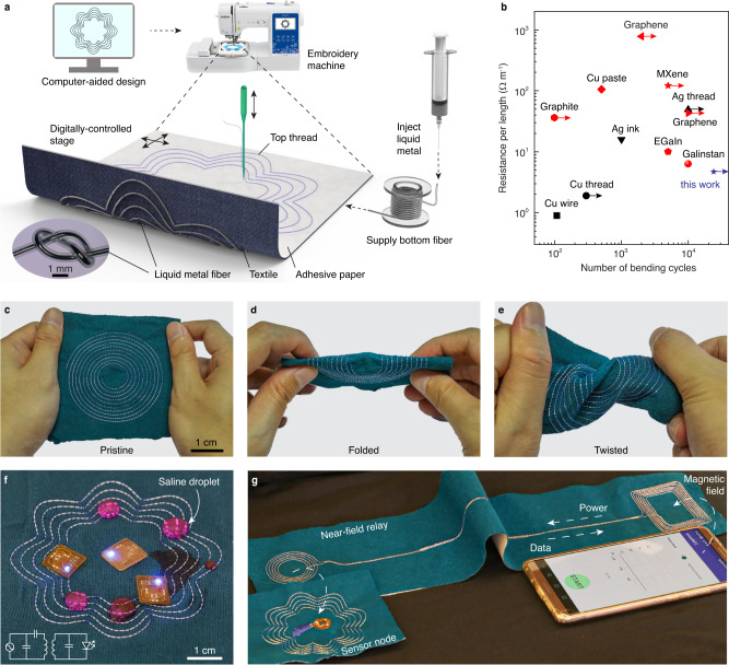
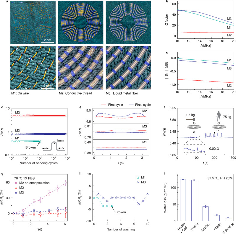
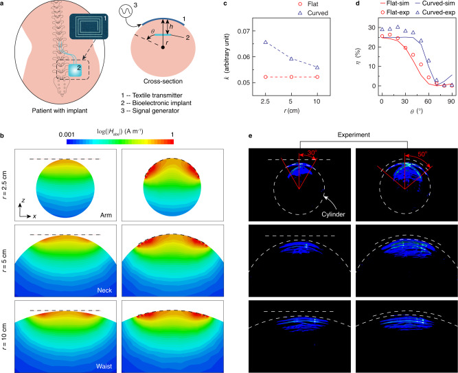
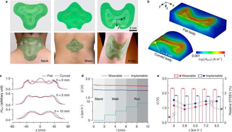
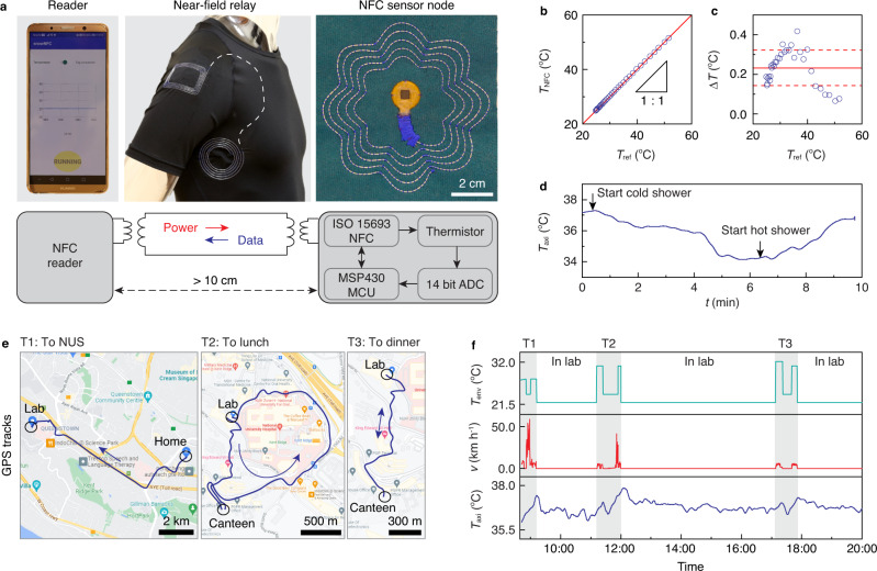
Electronic textiles capable of sensing, powering, and communication can be used to non-intrusively monitor human health during daily life. However, achieving these functionalities with clothing is challenging because of limitations in the electronic performance, flexibility and robustness of the underlying materials, which must endure repeated mechanical, thermal and chemical stresses during daily use. Here, we demonstrate electronic textile systems with functionalities in near-field powering and communication created by digital embroidery of liquid metal fibers. Owing to the unique electrical and mechanical properties of the liquid metal fibers, these electronic textiles can conform to body surfaces and establish robust wireless connectivity with nearby wearable or implantable devices, even during strenuous exercise. By transferring optimized electromagnetic patterns onto clothing in this way, we demonstrate a washable electronic shirt that can be wirelessly powered by a smartphone and continuously monitor axillary temperature without interfering with daily activities.
Overview
The claims and statistics of this paper haven’t been checked yet.
Run the check — free, no account needed. It reads the open-access text and checks the sources it cites.
Integrity signals
Registry
Cites
Statistics
Figures
Verification
Claims the paper makes
The claims and statistics of this paper haven’t been checked yet.
Run the check — free, no account needed. It reads the open-access text and checks the sources it cites.
Claims other papers make about this one
Each is checked against this paper’s own text: does it say what the citing paper says it does?
In the citing paper
“Near-field communication (NFC) offers an alternative approach where sensors can be wirelessly powered by a reader, enabling battery-free and secure operation for various physiological measurements on the skin or inside the body (Lin et al. 2020; Lin et al. 2022; Niu et al. 2019; Shi et al. 2022).”
From Artificial intelligence enhanced sensors - enabling technologies to next-generation healthcare and biomedical platform (2023) · cites this paper as Lin et al. 2022
Self-check
Percentages, sums and reported differences re-computed from the paper’s own numbers.
The self-check needs the paper’s full text.
Citations
Cites
Stretchable and Soft Electronics using Liquid Metals
Dickey, M. D. (2017) · Advanced Materials · doi:10.1002/adma.201606425 · Cited by 1,807
Large-area display textiles integrated with functional systems
Shi, X., Zuo, Y., Zhai, P., Shen, J., Yang, Y., Gao, Z., Liao, M., Wu, J., Wang, J., Xu, X., et al. (2021) · Nature · doi:10.1038/s41586-021-03295-8 · Cited by 1,113
Smart Textile‐Integrated Microelectronic Systems for Wearable Applications
Shi, J., Liu, S., Zhang, L., Yang, B., Shu, L., Yang, Y., Ren, M., Wang, Y., Chen, J., Chen, W., et al. (2019) · Advanced Materials · doi:10.1002/adma.201901958 · Cited by 844
Weng, W., Chen, P., He, S., Sun, X., & Peng, H. (2016) · Angewandte Chemie International Edition · doi:10.1002/anie.201507333 · Cited by 585
Mechanically Flexible Conductors for Stretchable and Wearable E‐Skin and E‐Textile Devices
Wang, B., & Facchetti, A. F. (2019) · Advanced Materials · doi:10.1002/adma.201901408 · Cited by 524
Advances in liquid metals for biomedical applications
Yan, J., Lü, Y., Chen, G., Yang, M., & Gu, Z. (2018) · Chemical Society Reviews · doi:10.1039/c7cs00309a · Cited by 518
Machine-knitted washable sensor array textile for precise epidermal physiological signal monitoring
Fan, W., He, Q., Meng, K., Tan, X., Zhou, Z., Zhang, G., Yang, J., & Wang, Z. L. (2020) · Science Advances · doi:10.1126/sciadv.aay2840 · Cited by 516
Wireless body sensor networks based on metamaterial textiles
Tian, X., Lee, P. M., Tan, Y. J., Wu, T. L. Y., Yao, H., Zhang, M., Li, Z., Ng, K. A., Tee, B. C. K., & Ho, J. S. (2019) · Nature Electronics · doi:10.1038/s41928-019-0257-7 · Cited by 444
Self-citationHighly stretchable multilayer electronic circuits using biphasic gallium-indium
Liu, S., Shah, D., & Kramer-Bottiglio, R. K. (2021) · Nature Materials · doi:10.1038/s41563-021-00921-8 · Cited by 420
Learning human–environment interactions using conformal tactile textiles
Luo, Y., Li, Y., Sharma, P., Shou, W., Wu, K., Foshey, M., Li, B., Palacios, T., Torralba, A., & Matusik, W. (2021) · Nature Electronics · doi:10.1038/s41928-021-00558-0 · Cited by 395
Research works printed but not linked: 1
- Beer, F. P., Johnston, E. R. & Dewolf, J. T. Mechanics of Materials. 3rd edn (McGraw-Hill, 2001).
Cited by
Sorted by citations
Technology Roadmap for Flexible Sensors
Luo, Y., Abidian, M. R., Ahn, J., Akinwande, D., Andrews, A. M., Antonietti, M., Bao, Z., Magnus Berggren, A., Berkey, C. A., Bettinger, C. J., et al. (2023) · ACS Nano · doi:10.1021/acsnano.2c12606 · Cited by 1,453
Self-citationWang, C., He, T., Zhou, H., Zhang, Z., & Lee, C. (2023) · Bioelectronic Medicine · doi:10.1186/s42234-023-00118-1 · Cited by 295
Porous Conductive Textiles for Wearable Electronics
Ding, Y., Jiang, J., Wu, Y., Zhang, Y., Zhou, J., Zhang, Y., Huang, Q., & Zheng, Z. (2024) · Chemical Reviews · doi:10.1021/acs.chemrev.3c00507 · Cited by 283
Kong, L., Li, W., Zhang, T., Ma, H., Cao, Y., Wang, K., Zhou, Y., Shamim, A., Zheng, L., Wang, X., et al. (2024) · Advanced Materials · doi:10.1002/adma.202400333 · Cited by 240
Smart Electronic Textile‐Based Wearable Supercapacitors
Islam, M. R., Afroj, S., Novoselov, K. S., & Karim, N. (2022) · Advanced Science · doi:10.1002/advs.202203856 · Cited by 216
Metadata
- Authors
- Lin, R., Kim, H.-J., Achavananthadith, S., Xiong, Z., Lee, J. K. W., Kong, Y. L., & Ho, J. S.
- Affiliations
- National University of Singapore (SG)
- Agency for Science, Technology and Research (SG)
- University of Utah (US)
- Corresponding author
- Kong, Yong Lin
- ORCID
- Venue
- Nature Communications
- Published
- 2022-04-21
- Volume
- 13
- Issue
- 1
- Pages
- 2190-2190
- ISSN
- 2041-1723 (ISSN-L)
- PMC
- PMC9023486
- OpenAlex
- W4224229286
- Semantic Scholar
- f825e617429690910b8b49a79acd1c9b13193597
- Cited by
- 267
- References
- 52
- Citations by year
- 2026: 50 · 2025: 67 · 2024: 71 · 2023: 68 · 2022: 11
- FWCI
- 15.75
- Type
- journal article
- Language
- en
- Open access
- gold
- doi.org
- Locations
- Nature Communications (publishedVersion, cc-by)
- PubMed Central (publishedVersion, cc-by)
- PubMed (publishedVersion)
- National University of Singapore (submittedVersion)
- RePEc: Research Papers in Economics (submittedVersion)
- DOAJ (DOAJ: Directory of Open Access Journals) (submittedVersion, cc-by-sa)
- Funders
- National Research Foundation Singapore (NRFF2017-07)
- Topics
- Physical Sciences › Engineering › Biomedical Engineering › Advanced Sensor and Energy Harvesting Materials
- Physical Sciences › Engineering › Electrical and Electronic Engineering › Nanomaterials and Printing Technologies
- Physical Sciences › Engineering › Electrical and Electronic Engineering › Wireless Power Transfer Systems
- Keywords
- smart textiles, digital embroidery, wireless communication, health monitoring, flexible electronics
- MeSH terms
- Wearable Electronic Devices, Electronics, Humans, Metals, Monitoring, Physiologic, Textiles
About these checks
Registry, retraction, Cites and statistics results are computed, not judged, with one exception: a printed reference that no index lists is read once by a model before it counts as a citation error. Claims are extracted by a model and kept only when their quote appears verbatim in the text; each cited source is then checked, with a model’s help, for whether it says what the claim relies on. Those verdicts can be wrong — read the claim’s quote and the cited source before relying on one.
Statistics and arithmetic are recomputed, not judged.
Confidence bands are shown only for fields calibrated on our annotated test set. None is calibrated yet, so no band is shown.
What counts as a claim ›How we measure confidence ›How we check this ›
Are you an author, or do you see a problem with this page? Request a review
