

The DOI matches its Crossref record; 17 of the 18 references it cites were found in a registry or an index; 1 of the 17 sources its claims cite were checked for support.
Controller Hardware-in-the-loop (C-HIL) Testing of Decentralized EV-Grid Integration
Open accessAbstract
Present grid infrastructure is unprepared for the wide-scale integration of electric vehicles (EVs). Real-time grid simulation and hardware testing are necessary for the fast and accurate development of EV charging control strategies that are applicable in the field to mitigate their adverse effects. To help facilitate this goal, in this study, we develop a controller verification testbed using a baseline bidirectional AC/DC converter, commonly used in on-board EV chargers, within a hardware-in -the-loop (HIL) test system. The converter runs real-time on a very-fast time scale and integrates into an external grid simulator. We utilize the strength of the HIL device in simulating power electronics while simultaneously realizing a complex distribution grid operation in real-time. The whole system holistically provides an opportunity to see the implementation benefits of a decentralized charging algorithm on the voltage stability of the distribution grid. The study presents a step-by-step approach to developing and testing controllers, providing an essential contribution in the field demonstration of decentralized EV charger control strategies.
Overview
CoChat Summary
TL;DR
The paper develops a controller hardware-in-the-loop testbed for a bidirectional AC/DC on-board EV charger and integrates it with a real-time distribution-grid simulator. It shows that a decentralized AIMD charging controller can reduce node voltage drop during peak loading, at the cost of a large reduction in average charging power.
Key findings
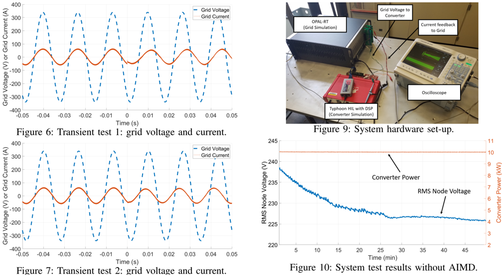
- The converter controller tracked step changes at rated 10 kVA: Test #1 shifted from 10 kW/0 kVAR to 7.07 kW/7.07 kVAR (0.707 pf lagging), and Test #2 shifted to 7.07 kW/−7.07 kVAR (0.707 pf leading), with successful transient performance.
- In a 50-minute constant-power test, the grid node voltage fell to approximately 226 V RMS while the charger drew 10 kW.
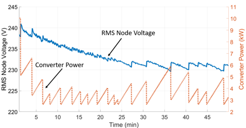
- With the decentralized AIMD algorithm, the node voltage dropped only to a minimum of about 229 V RMS, but the charger operated at an average power of 3.9 kW, a 61% drop in charging power.
- The AIMD algorithm ran without considerable extra taxation to the TI DSP closed-loop computation, supporting easy implementation at the charger end-node.
Methods
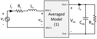
- A baseline bidirectional AC/DC converter with full-bridge active front-end rectifier and resistor DC load was modeled and controlled; system specs included 10 kVA, 240 V grid, 72 kHz switching, 500 µH filter inductance, 340–800 V DC output, 500 µF output capacitance, and 60 Ω output equivalent resistance.
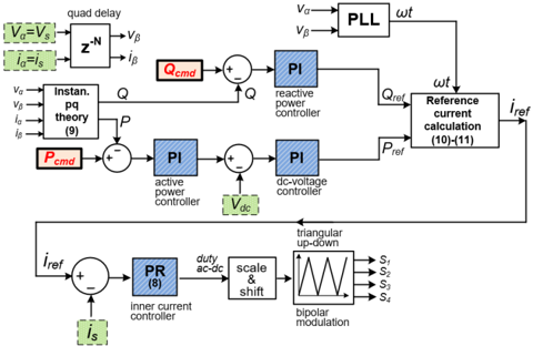
- The controller used an inner proportional-resonant current loop and outer discrete PI loops for active power, reactive power, and DC bus voltage; P-Q measurements used single-phase P-Q theory with a 20 Hz low-pass filter.
- The converter ran on a Typhoon HIL 402, was controlled by a TI TMS320F28335 DSP, and was integrated with an OPAL-RT OP5600 real-time grid simulator modeling a 2.5 MVA, 230 kV/4.8 kV, 37-bus distribution network with 10 neighborhoods of 16 homes each, totaling 320 end-nodes.
Limitations
- Stated: the authors plan future work to construct a hardware version of the converter for high-power testing, accurate loss measurements, and analysis of HIL simulation accuracy; they also note that simulation alone can omit real-world controller implementation problems.
- Evident from the text: only the AC/DC stage is analyzed, with a resistor emulating battery charging rather than an actual battery pack or DC/DC stage.
- Evident from the text: the grid-integration test places one EV charger in one of 16 homes within one neighborhood, and the grid model is a balanced three-phase network, so broader multi-charger and unbalanced conditions are not demonstrated.
Model-written summary. Check it against the paper before relying on it.
Integrity signals
Registry
Cites
Statistics
Figures



Verification
Claims the paper makes
1 Valid · 4 Not valid · 12 Not checked · 24 Own results and interpretations
Every source the paper cites for this claim was checked and supports it.
In the paper
“There has also been limited work in real-time control algorithm validation, but with control algorithms different than AIMD [13].”
What the sources say
- Supportedcites [13] source
Section 5 (page not provided) says transitioning from software simulation to hardware-in-the-loop evaluation is rarely done. Sections 1 and 3 identify this paper’s evaluated algorithm as P-MARL, a reinforcement-learning approach rather than AIMD; Section 4.3.2 describes its hardware-in-the-loop evaluation. (LLM, conf=0.86)
plain- Asserted: passes — The authors put it forward as true.
- Checkable: passes — It can be checked against evidence.
- Load-bearing: passes — The paper’s conclusions depend on it.
- Based: passes — The paper gives a reason why it holds.
- Supported
A result the paper reports from its own data — it cites no other source for it, so there is none to check. The quote shows it is in the paper.
In the paper
“In about 50 minutes of the constant power test, the grid voltage had fallen to approximately 226 V RMS with a charging power of 10 kW.”
plainstates an associationSingle case- Asserted: passes — The authors put it forward as true.
- Checkable: passes — It can be checked against evidence.
- Load-bearing: passes — The paper’s conclusions depend on it.
- Based: passes — The paper gives a reason why it holds.
A result the paper reports from its own data — it cites no other source for it, so there is none to check. The quote shows it is in the paper.
In the paper
“When the AIMD algorithm is used, the grid node voltage only dropped to a minimum of about 229 V RMS , but the charger was only able to operate at an average power of 3.9 kW.”
plainstates a cause- Asserted: passes — The authors put it forward as true.
- Checkable: passes — It can be checked against evidence.
- Load-bearing: passes — The paper’s conclusions depend on it.
- Based: passes — The paper gives a reason why it holds.
A result the paper states — it cites no source for it, so there is none to check. The quote shows it is in the paper.
In the paper
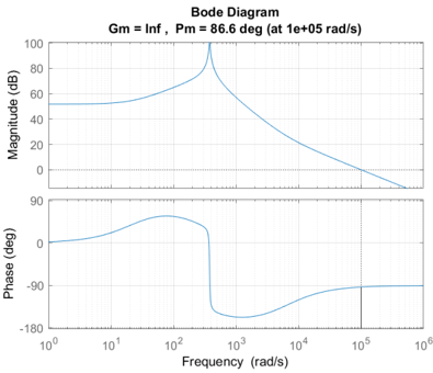
“After inserting a gain of 0.1 in the controller path to slow down the response, the cross-over frequency of the new system with the PR controller is now 100 krad/s.”
plainstates a cause- Asserted: passes — The authors put it forward as true.
- Checkable: passes — It can be checked against evidence.
- Load-bearing: unclear — It is unclear whether the paper’s conclusions depend on it.
- Based: passes — The paper gives a reason why it holds.
A result the paper reports from its own data — it cites no other source for it, so there is none to check. The quote shows it is in the paper.
In the paper
“When the AIMD algorithm is used, the grid node voltage only dropped to a minimum of about 229 V RMS , but the charger was only able to operate at an average power of 3.9 kW.”
plainstates a causeSingle case- Asserted: passes — The authors put it forward as true.
- Checkable: passes — It can be checked against evidence.
- Load-bearing: passes — The paper’s conclusions depend on it.
- Based: passes — The paper gives a reason why it holds.
17 more claims
Create a free account to see all 41 claims and to verify the 1 reference still open.
- It may state two separate claims as one. 6
- The quote only partly states this claim. 2
- Probably not a substantial claim. 14
Citations
Cites
Regression analysis for prediction of residential energy consumption
Fumo, N., & Rafe Biswas, M. A. (2015) · Renewable and Sustainable Energy Reviews · doi:10.1016/j.rser.2015.03.035 · Cited by 630
Single-Phase On-Board Bidirectional PEV Charger for V2G Reactive Power Operation
Kisacikoglu, M. C., Kesler, M., & Tolbert, L. M. (2015) · IEEE Transactions on Smart Grid · doi:10.1109/tsg.2014.2360685 · Cited by 381
Self-citationEV/PHEV Bidirectional Charger Assessment for V2G Reactive Power Operation
Kisacikoglu, M. C., Ozpineci, B., & Tolbert, L. M. (2013) · IEEE Transactions on Power Electronics · doi:10.1109/tpel.2013.2251007 · Cited by 291
Self-citationA comparison of electric vehicle Level 1 and Level 2 charging efficiency
Sears, J., Roberts, D., & Glitman, K. (2014) · IEEE Conference on Technologies for Sustainability · doi:10.1109/sustech.2014.7046253 · Cited by 109
Haque, M. T. (2003) · 2002 IEEE 33rd Annual IEEE Power Electronics Specialists Conference. Proceedings (Cat. No.02CH37289) · doi:10.1109/psec.2002.1023074 · Cited by 91
A unified multi-functional on-board EV charger for power-quality control in household networks
Taghizadeh, S., Hossain, M. J., Lu, J., & Water, W. (2018) · Applied Energy · doi:10.1016/j.apenergy.2018.02.006 · Cited by 53
(2013) · Cited by 39
Self-citationEnhanced AIMD-based decentralized residential charging of EVs
Liu, M., & McLoone, S. (2015) · Transactions of the Institute of Measurement and Control · doi:10.1177/0142331213494100 · Cited by 36
Chattopadhyay, R., De, A., & Bhattacharya, S. (2014) · 2014 IEEE Energy Conversion Congress and Exposition (ECCE) · doi:10.1109/ecce.2014.6953895 · Cited by 35
Jayawardana, I., Ho, C. N. M., & Zhang, Y. (2022) · IEEE Journal of Emerging and Selected Topics in Power Electronics · doi:10.1109/jestpe.2021.3093303 · Cited by 35
Research works printed but not linked: 3
- Voelcker, 2021, Jd power study: Electric vehicle owners prefer dedicated home charging stations
- 2021, Typhoon hi1402
- 2021, Opal-RT Technologies
Cited by
Ali, R., Liu, R., Nayyar, A., et al. (2023) · IEEE Access · doi:10.1109/access.2023.3234964 · Cited by 30
EV Smart Charging in Distribution Grids–Experimental Evaluation Using Hardware in the Loop Setup
Yu, Y., Herdt, L. D., Shekhar, A., Mouli, G. R. C., & Bauer, P. (2024) · IEEE Open Journal of the Industrial Electronics Society · doi:10.1109/ojies.2024.3352265 · Cited by 16
Design and Implementation of a Hardware Test-bed for Real-time EV-Grid Integration Analysis
Ucer, E. Y., & Kisacikoglu, M. C. (2022) · IEEE Energy Conversion Congress and Exposition (ECCE) · doi:10.1109/ecce50734.2022.9947704 · Cited by 6
Self-citationLosada-Gutiérrez, C., Espinosa, F., Cruz, C., et al. (2025) · Actuators · doi:10.3390/act14080376 · Cited by 4
Amoura, N., Rahoui, A., Boukais, B., et al. (2025) · Electronics · doi:10.3390/electronics14183620 · Cited by 3
Metadata
- Authors
- Flack, C., Ucer, E., Smith, C. P., & Kisacikoglu, M.
- Affiliations
- University of Alabama (US)
- Venue
- 2022 IEEE Power & Energy Society General Meeting (PESGM)
- Publisher
- IEEE
- Published
- 2022-07-17
- Pages
- 01-05
- ISSN
- 1932-5517 (ISSN-L)
- OpenAlex
- W4312435462
- Cited by
- 13
- References
- 18
- Citations by year
- 2026: 3 · 2025: 5 · 2024: 1 · 2023: 3 · 2022: 1
- FWCI
- 3.82
- Type
- conference paper
- Language
- en
- Open access
- green
- arxiv.org
- Locations
- IEEE Power Engineering Society General Meeting (publishedVersion)
- arXiv (Cornell University) (submittedVersion, cc-by-nc-nd)
- arXiv (Cornell University)
- Funders
- National Science Foundation (1755996)
- Topics
- Physical Sciences › Engineering › Control and Systems Engineering › Real-time simulation and control systems
- Physical Sciences › Engineering › Electrical and Electronic Engineering › Electric Vehicles and Infrastructure
- Physical Sciences › Engineering › Control and Systems Engineering › Microgrid Control and Optimization
- Keywords
- electric vehicle charging, hardware-in-the-loop testing, EV grid integration, bidirectional AC-DC converter, controller verification, power electronics testing
About these checks
Registry, retraction, Cites and statistics results are computed, not judged, with one exception: a printed reference that no index lists is read once by a model before it counts as a citation error. Claims are extracted by a model and kept only when their quote appears verbatim in the text; each cited source is then checked, with a model’s help, for whether it says what the claim relies on. Those verdicts can be wrong — read the claim’s quote and the cited source before relying on one.
A language model drew the claims from the paper on 2026-10-10, under version 3 of the claim definition (model deepseek-v4.1-flash, prompt extract-v3).
A second model labelled each claim on 2026-10-10 (model jev-1.13-20260917, definition revision gold-guideline-v0.2).
Cited sources are checked with a language model’s help (gpt-6-sol).
Statistics and arithmetic are recomputed, not judged.
Confidence bands are shown only for fields calibrated on our annotated test set. None is calibrated yet, so no band is shown.
What counts as a claim ›How we measure confidence ›How we check this ›
Are you an author, or do you see a problem with this page? Request a review
How to cite
Cite CoChat for the checks on this page, and the paper for its own findings.
- This page
- CoChat. (2026). Citation check: Controller Hardware-in-the-loop (C-HIL) Testing of Decentralized EV-Grid Integration. https://app.cochat.ai/papers/10.1109/pesgm48719.2022.9917135
- The paper
- Flack, C., Ucer, E., Smith, C. P., & Kisacikoglu, M. (2022). Controller Hardware-in-the-loop (C-HIL) Testing of Decentralized EV-Grid Integration. 2022 IEEE Power & Energy Society General Meeting (PESGM). https://doi.org/10.1109/pesgm48719.2022.9917135
Data sources
Bibliographic data: Semantic Scholar, OpenAlex, Crossref.
Contains information from the Semantic Scholar Academic Graph Datasets, made available under the ODC Attribution License (ODC-BY 1.0).
Semantic Scholar’s data is described in: Kinney, R., et al. (2023). The Semantic Scholar Open Data Platform. arXiv:2301.10140.
