

The DOI matches its Crossref record; the references it cites are not checked yet.
Reduction of eddy current losses in inductive transmission systems with ferrite sheets
Open accessAbstract
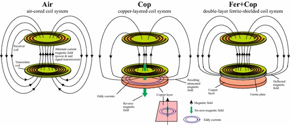
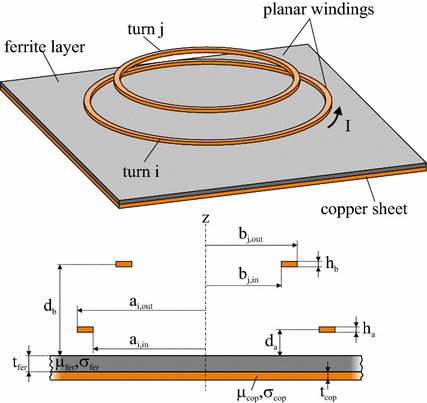
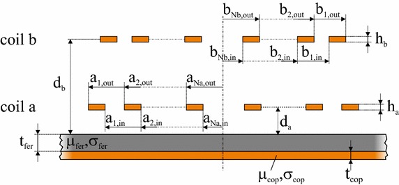
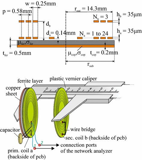
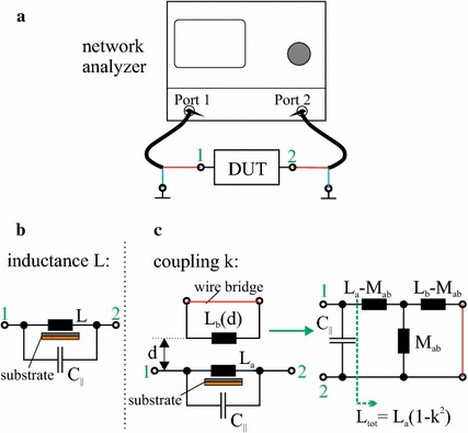
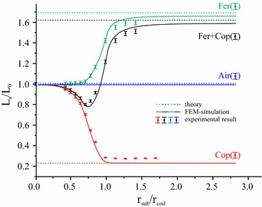
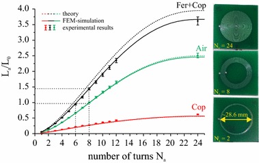
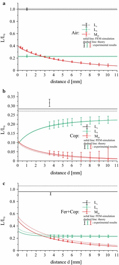
BACKGROUND: Improvements in eddy current suppression are necessary to meet the demand for increasing miniaturization of inductively driven transmission systems in industrial and biomedical applications. The high magnetic permeability and the simultaneously low electrical conductivity of ferrite materials make them ideal candidates for shielding metallic surfaces. For systems like cochlear implants the transmission of data as well as energy over an inductive link is conducted within a well-defined parameter set. For these systems, the shielding can be of particular importance if the properties of the link can be preserved. RESULTS: In this work, we investigate the effect of single and double-layered substrates consisting of ferrite and/or copper on the inductance and coupling of planar spiral coils. The examined link systems represent realistic configurations for active implantable systems such as cochlear implants. Experimental measurements are complemented with analytical calculations and finite element simulations, which are in good agreement for all measured parameters. The results are then used to study the transfer efficiency of an inductive link in a series-parallel resonant topology as a function of substrate size, the number of coil turns and coil separation. CONCLUSIONS: We find that ferrite sheets can be used to shield the system from unwanted metallic surfaces and to retain the inductive link parameters of the unperturbed system, particularly its transfer efficiency. The required size of the ferrite plates is comparable to the size of the coils, which makes the setup suitable for practical implementations. Since the sizes and geometries chosen for the studied inductive links are comparable to those of cochlear implants, our conclusions apply in particular to these systems.
Overview
The claims and statistics of this paper haven’t been checked yet.
Run the check — free, no account needed. It reads the open-access text and checks the sources it cites.
Integrity signals
Registry
Cites
Statistics
Figures
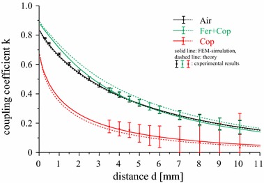
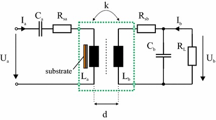
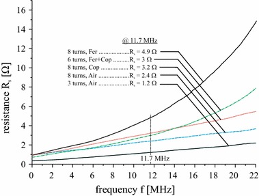
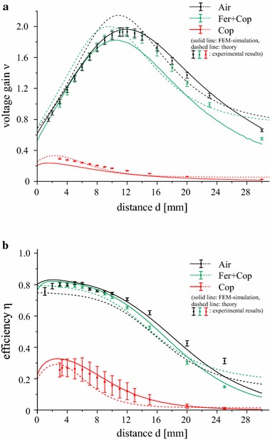
Verification
Claims the paper makes
The claims and statistics of this paper haven’t been checked yet.
Run the check — free, no account needed. It reads the open-access text and checks the sources it cites.
Claims other papers make about this one
Each is checked against this paper’s own text: does it say what the citing paper says it does?
The source backs part of the claim, not all of it — or backs it for a different population, condition or comparison.
In the citing paper
“This range minimizes eddy current losses, thereby reducing the risk of localized heating and its subsequent influence on neural stability (Maaß et al., 2017; Haerinia and Shadid, 2020; Mahmood et al., 2022).”
From Comparative analysis of energy transfer mechanisms for neural implants (2024) · cites this paper as Maaß et al., 2017
Experimental — accuracy not yet measured
Self-check
Percentages, sums and reported differences re-computed from the paper’s own numbers.
The self-check needs the paper’s full text.
Citations
The citation lists haven’t been fetched yet
References 23 · Cited by 16
Research works printed but not linked: 21
- Hui SY. Planar wireless charging technology for portable electronic products and Qi. Proc IEEE. 2013;101(6):1290–301. · DOI
- Yilmaz M, Krein PT. Review of battery charger topologies, charging power levels, and infrastructure for plug-in electric and hybrid vehicles. IEEE Trans Power Electron. 2013;28(5):2151–69. · DOI · Paper page
- Mohagheghi S, Parkhideh B, Bhattacharya S. Inductive power transfer for electric vehicles: potential benefits for the distribution grid. In: Electric Vehicle Conference (IEVC), 2012 IEEE International; March 2012. p. 1–8. · DOI
- Mukhopadhyay SC, Gupta GS, Lake BJ. Design of a contactless battery charger for micro-robots. In: IEEE IMTC proceedings; 2008. p. 985–90. · DOI
- Assaf T, Stefanini C, Dario P. Autonomous underwater biorobots. IEEE Robot Autom Mag. 2013;20(3):26–32. · DOI
- Scholz P, Reinhold C, John W, Hilleringmann U. Analysis of energy transmission for inductive coupled RFID tags. In: 2007 IEEE International Conference on RFID; 2007. p. 100–107. · DOI
- Jonah O, Georgakopoulos SV. Wireless power transmission to sensors in reinforced concrete via magnetic resonance. In: IEEE antennas propagation; 2012. · DOI
- De Clercq H, Puers R. A wireless energy transfer platform, integrated at the bedside. In: IEEE Engineering in Medicine and Biology; 2013. p. 1458–61. · DOI
- Hochmair ES. System optimization for improved accuracy in transcutaneous signal and power transmission. IEEE Trans Biomed Eng. 1984;31(2):177–86. · DOI
- Zierhofer CM, Hochmair ES. High-efficiency coupling-insensitive transcutaneous power and data transmission via an inductive link. IEEE Trans Biomed Eng. 1990;37(7):716–22. · DOI
- Galbraith DC, Soma M, White RL. A wide-band efficient inductive transdermal power and data link with coupling insensitive gain. IEEE Trans Biomed Eng. 1987;34(4):265–75. · DOI
- Stoll RL. The analysis of eddy currents. Oxford: Oxford University Press; 1974.
- Ahn S, Hwang C, Park HH. Optimized shield design for reduction of EMF from wireless power transfer systems. IEICE Electron Express. 2014;11(2):1–9.
- Schormans M, Valente V, Demosthenous A. Frequency splitting analysis and compensation method for inductive wireless powering of implantable biosensors. Sensors. 2016;16(8):1–14. · DOI
- Su YP, Liu X, Hui SY. Extended theory on the inductance calculation of planar spiral windings including the effect of double-layer electromagnetic shield. IEEE Trans Power Electron. 2008;23(4):2052–61. · DOI
- Rodriguez R, Dishman JM, Dickens FT, Whelan EW. Modeling of two-dimensional spiral inductors. IEEE Trans Compon Hybrids Manuf Technol. 1980;3(4):535–41. · DOI
- Roshen WA, Turcotte DE. Planar inductors on magnetic substrates. IEEE Trans Magn. 1988;24(6):3213–6. · DOI
- Hurley WG, Duffy MC. Calculation of self and mutual impedances in planar magnetic-structures. IEEE Trans Magn. 1995;31(4):2416–22. · DOI
- Zierhofer CM, Hochmair ES. Geometric approach for coupling enhancement of magnetically coupled coils. IEEE Trans Biomed Eng. 1996;43(7):708–14. · DOI
- Howe GWO. The calibration of wave-meters for radio- telegraphy. Proc Phys Soc Lond. 1912;24:251–9. · DOI
- Leuerer T, Mokwa W. Planar coils with magnetic layers for optimized energy transfer in telemetric systems. Sens Actuators Phys. 2004;116(3):410–6. · DOI
Metadata
- Authors
- Maaß, M., Griessner, A., Steixner, V., & Zierhofer, C.
- Affiliations
- Universität Innsbruck (AT)
- Corresponding author
- Griessner, Andreas
- Venue
- BioMedical Engineering OnLine
- Published
- 2017-01-05
- Volume
- 16
- Issue
- 1
- Pages
- 3-3
- ISSN
- 1475-925X (ISSN-L)
- PMC
- PMC5234259
- OpenAlex
- W2574893335
- Cited by
- 16
- References
- 23
- Citations by year
- 2026: 3 · 2024: 3 · 2023: 2 · 2022: 1 · 2021: 2 · 2020: 1 · 2019: 1 · 2018: 2 · 2017: 1
- FWCI
- 0.57
- Type
- journal article
- Language
- en
- Open access
- gold
- doi.org
- Licence
- cc-by
- Locations
- BioMedical Engineering OnLine (publishedVersion, cc-by)
- PubMed Central (publishedVersion, cc-by)
- PubMed (publishedVersion)
- Digital Library of the University of Innsbruck (University of Innsbruck) (submittedVersion, cc-by)
- Funders
- Universität Innsbruck
- MED-EL Medical Electronics
- Topics
- Physical Sciences › Engineering › Electrical and Electronic Engineering › Wireless Power Transfer Systems
- Physical Sciences › Engineering › Electrical and Electronic Engineering › Induction Heating and Inverter Technology
- Physical Sciences › Engineering › Biomedical Engineering › Wireless Body Area Networks
- Keywords
- eddy current loss, ferrite sheet, inductive power transfer, cochlear implants, active implantable medical devices, planar spiral coil, magnetic shielding, transfer efficiency, inductive coupling, coil inductance, copper substrate
- MeSH terms
- Copper, Electric Conductivity, Ferric Compounds, Finite Element Analysis, Magnetic Fields
About these checks
Registry, retraction, Cites and statistics results are computed, not judged, with one exception: a printed reference that no index lists is read once by a model before it counts as a citation error. Claims are extracted by a model and kept only when their quote appears verbatim in the text; each cited source is then checked, with a model’s help, for whether it says what the claim relies on. Those verdicts can be wrong — read the claim’s quote and the cited source before relying on one.
Statistics and arithmetic are recomputed, not judged.
Confidence bands are shown only for fields calibrated on our annotated test set. None is calibrated yet, so no band is shown.
What counts as a claim ›How we measure confidence ›How we check this ›
Are you an author, or do you see a problem with this page? Request a review
How to cite
Cite CoChat for the checks on this page, and the paper for its own findings.
- This page
- CoChat. (2026). Citation check: Reduction of eddy current losses in inductive transmission systems with ferrite sheets. https://app.cochat.ai/papers/10.1186/s12938-016-0297-4
- The paper
- Maaß, M., Griessner, A., Steixner, V., & Zierhofer, C. (2017). Reduction of eddy current losses in inductive transmission systems with ferrite sheets. BioMedical Engineering OnLine. https://doi.org/10.1186/s12938-016-0297-4
