PreprintCited by 60Bacterial Genetics and BiotechnologyAdvanced Electron Microscopy Techniques and ApplicationsATP Synthase and ATPases Research

The DOI matches its Crossref record; 1 of the 1 references it cites were found in a registry or an index.

Structural Basis of Directional Switching by the Bacterial Flagellum

Open access

Preprint — published as 10.1038/s41564-024-01630-z

Abstract

The bacterial flagellum is a macromolecular protein complex that harvests energy from ion-flow across the inner membrane to power bacterial swimming in viscous fluids via rotation of the flagellar filament. Bacteria such as Salmonella enterica are capable of bi-directional flagellar rotation even though ion flow is uni-directional. How uni-directional ion-movement through the inner membrane is utilized by this macromolecular machine to drive bi-directional flagellar rotation is not understood, but a chemotactic response regulator in the cytoplasm is known to reverse the direction of rotation. We here present cryo-EM structures of intact Salmonella flagellar basal bodies, including the cytoplasmic complexes required for power transmission, in conformations representing both directions of rotation. The structures reveal that the conformational changes required for switching the direction of rotation involve 180 degree rotations of both the N- and C-terminal domains of the FliG protein. Combining these models with a new, high-resolution, cryo-EM structure of the MotA5B2 stator, in complex with the C-terminal domain of FliG, reveals how uni-directional ion-flow across the inner membrane is used to accomplish bi-directional rotation of the flagellum.

Overview

The claims and statistics of this paper haven’t been checked yet.

Run the check — free, no account needed. It reads the open-access text and checks the sources it cites.

A few free checks a day · papers already verified open instantly · results are public

Integrity signals

Registry

Crossref · 10.21203/rs.3.rs-3417165/v1

Cites

1 of 1 references verified0 citation errors · 0 not checkable

Statistics

Figures

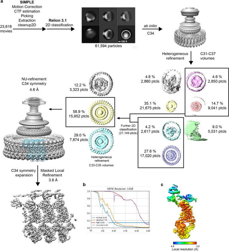
Extended Data Figure 1. Cryo-EM processing workflow, showing local and global map quality for the CCW C-ring structure. a, Image processing workflow for the CCW C-ring. b, Gold-standard FSC curves used for global-resolution estimates within cryoSPARC. c, Local-resolution estimation of reconstructed map as determined within cryoSPARC.
Extended Data Figure 1. Cryo-EM processing workflow, showing local and global map quality for the CCW C-ring structure. a, Image processing workflow for the CCW C-ring. b, Gold-standard FSC curves used for global-resolution estimates within cryoSPARC. c, Local-resolution estimation of reconstructed map as determined within cryoSPARC.CC BY · PubMed Central
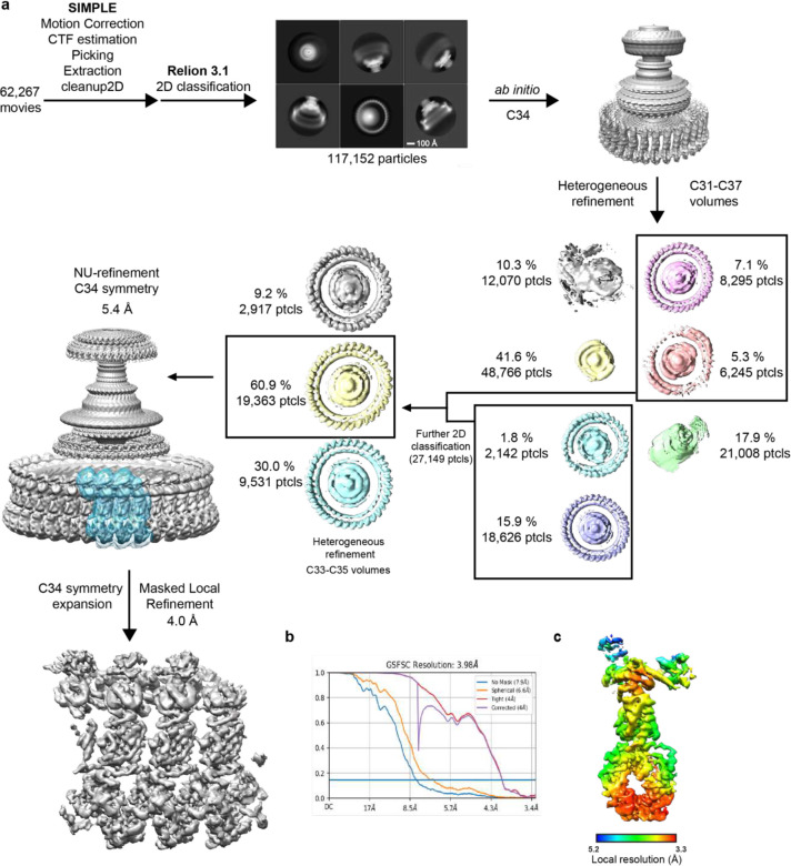
Extended Data Figure 2. Cryo-EM processing workflow, showing local and global map quality for the CW C-ring structure. a, Image processing workflow for the CW C-ring. b, Gold-standard FSC curves used for global-resolution estimates within cryoSPARC. c, Local-resolution estimation of reconstructed map as determined within cryoSPARC.
Extended Data Figure 2. Cryo-EM processing workflow, showing local and global map quality for the CW C-ring structure. a, Image processing workflow for the CW C-ring. b, Gold-standard FSC curves used for global-resolution estimates within cryoSPARC. c, Local-resolution estimation of reconstructed map as determined within cryoSPARC.CC BY · PubMed Central
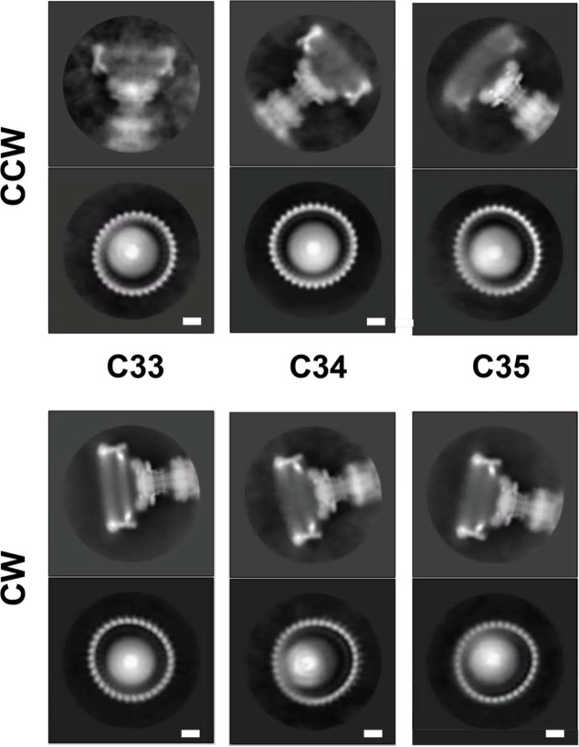
Extended Data Figure 3. Different Symmetries are apparent in 2D classes following particle classification in 3D 2D class averages are shown for CCW and CW particles separated into different symmetries via 3D classification. An example of a side-view is shown above and a top-down view below. The subunit numbers in the top-down views can be counted to reveal a symmetry consistent with the 3D classification.
Extended Data Figure 3. Different Symmetries are apparent in 2D classes following particle classification in 3D 2D class averages are shown for CCW and CW particles separated into different symmetries via 3D classification. An example of a side-view is shown above and a top-down view below. The subunit numbers in the top-down views can be counted to reveal a symmetry consistent with the 3D classification.CC BY · PubMed Central
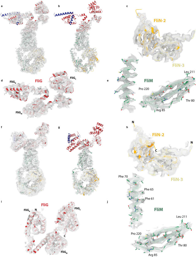
Extended Data Figure 4. Fit of coordinates to CCW and CW cryoEM volumes a-e, show different views at different contour levesl of the CCW coordinates within the CCW volume. f-j, show the same for the CCW volume. a,b and f,g show the full subunits (CCW and CW respectively) at a lower (a,f) and higer (b,g) contour levels revealing the FliG domains at the top of the subunit are the most mobile regions. c,h depict the volume surrounding two of the three FliN domains, d,i the volume around FliG and e,j for two regions of FliM, all for CCW and CW respectively.
Extended Data Figure 4. Fit of coordinates to CCW and CW cryoEM volumes a-e, show different views at different contour levesl of the CCW coordinates within the CCW volume. f-j, show the same for the CCW volume. a,b and f,g show the full subunits (CCW and CW respectively) at a lower (a,f) and higer (b,g) contour levels revealing the FliG domains at the top of the subunit are the most mobile regions. c,h depict the volume surrounding two of the three FliN domains, d,i the volume around FliG and e,j for two regions of FliM, all for CCW and CW respectively.CC BY · PubMed Central
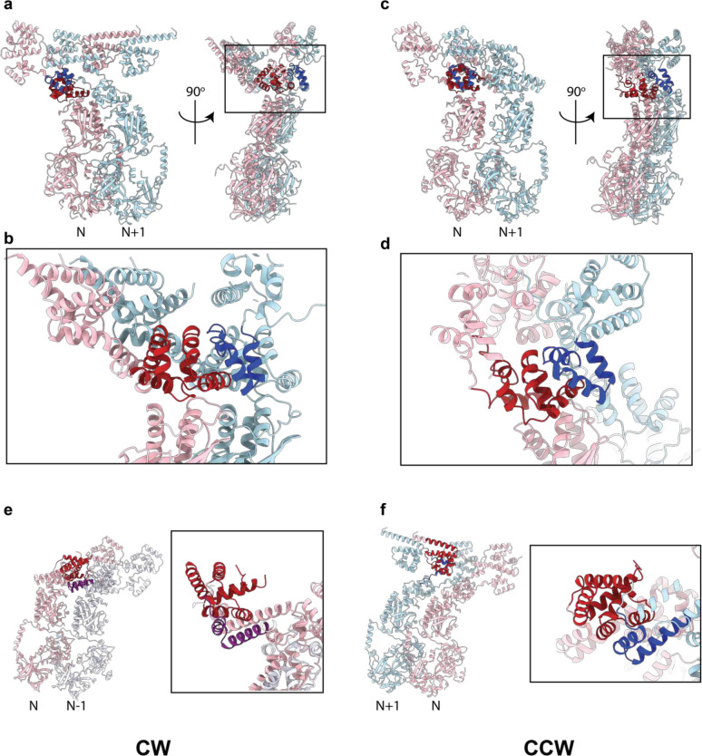
Extended Data Figure 5. Domain swaps between C-ring subunits involving regions of FliG Two neighbouring C-ring subunits are shown in cartoon representation coloured pink (copy N) and either light blue (N+1) or lavender (N−1). a,b,e, are from the CW assembly and c,d,e from the CCW. a-d, depict the domain swap to assemble the FliGM domain (dark red and dark blue to denote which subunit the sequences originate in). e-f depict the domain swap to assemble FliGN (coloured dark red and purple (e) or dark red and dark blue (f)).
Extended Data Figure 5. Domain swaps between C-ring subunits involving regions of FliG Two neighbouring C-ring subunits are shown in cartoon representation coloured pink (copy N) and either light blue (N+1) or lavender (N−1). a,b,e, are from the CW assembly and c,d,e from the CCW. a-d, depict the domain swap to assemble the FliGM domain (dark red and dark blue to denote which subunit the sequences originate in). e-f depict the domain swap to assemble FliGN (coloured dark red and purple (e) or dark red and dark blue (f)).CC BY · PubMed Central
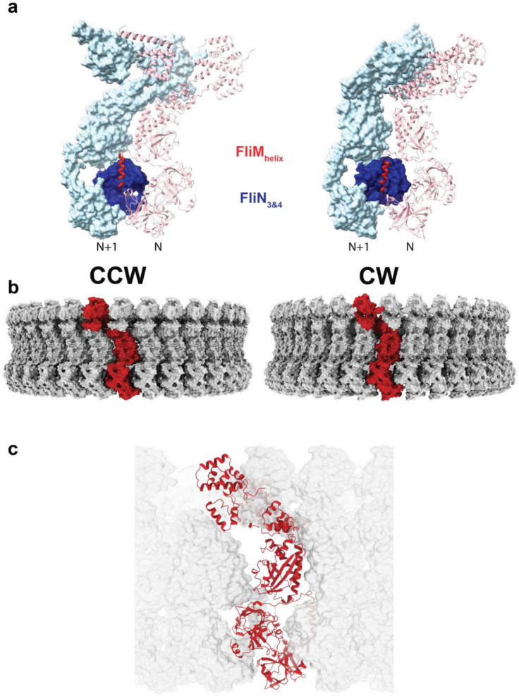
Extended Data Figure 6. Complexity of Subunit Packing within the CCW and CW C-rings a, An unanticipated packing between a secondary structural element immediately following the FliMM domain leads to further inter-subunit packing interactions between FliM and FliN in addition to the previously proposed lock-washer interactions. This new element occurs in both states with subtly different contacts. b, A single subunit is colored red in the context of the C34 C-ring in both states to emphasise how the vertical subunits visible in previous low resolution volumes are constructed from domains originated in multiple subunits. c, A subunit taken from a CW state (red ribbon) is incompatible with packing between subunits in the CCW states reinforcing the cooperativity in switching states that must exist.
Extended Data Figure 6. Complexity of Subunit Packing within the CCW and CW C-rings a, An unanticipated packing between a secondary structural element immediately following the FliMM domain leads to further inter-subunit packing interactions between FliM and FliN in addition to the previously proposed lock-washer interactions. This new element occurs in both states with subtly different contacts. b, A single subunit is colored red in the context of the C34 C-ring in both states to emphasise how the vertical subunits visible in previous low resolution volumes are constructed from domains originated in multiple subunits. c, A subunit taken from a CW state (red ribbon) is incompatible with packing between subunits in the CCW states reinforcing the cooperativity in switching states that must exist.CC BY · PubMed Central
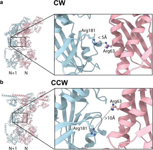
Extended Data Figure 7. FliM arginines that favour CW rotation when mutated are proximal in the CW but not the CCW state a, FliM Arginine 63 and 181 from the N and N+1 subunits respectively, are proximal to each other at the subunit interface in the CW state, b, but are separated in the CCW state.
Extended Data Figure 7. FliM arginines that favour CW rotation when mutated are proximal in the CW but not the CCW state a, FliM Arginine 63 and 181 from the N and N+1 subunits respectively, are proximal to each other at the subunit interface in the CW state, b, but are separated in the CCW state.CC BY · PubMed Central
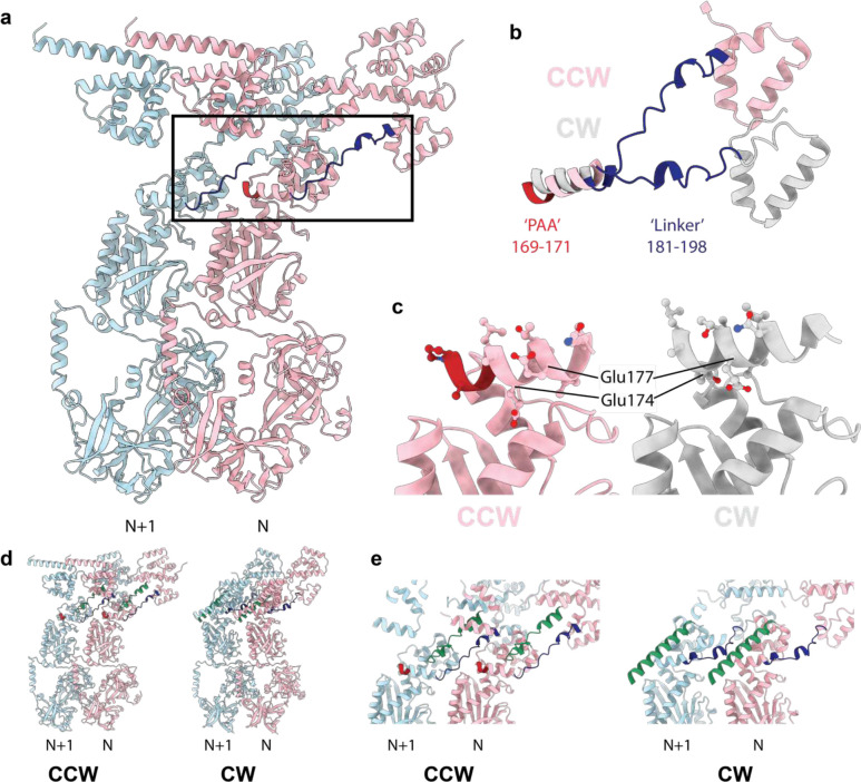
Extended Data Figure 8. Structural Implications of the PAA CW-locking mutation a, Two subunits in the CCW states are shown colored light pink (N) and light blue (N+1) with the FliG PAA sequence that, when deleted, locks the C-ring in the CW state highlighted in dark red and the FliG linker between FliGM and FliGC highlighted in dark blue. b, When the FliGM domains are used to overlay the CCW (light pink) and CW (silver) states the deletion of the PAA sequence (dark red in the CW state) leads to a pulling-up of that helix and reorientation of the FliGM-FliGC linker. c, overlaying the CCW (light pink) and CW (silver) by matching of the FliMM domain reveals how the FliGM helix containing the PAA sequence (dark red in the CCW state), is reoriented altering the side chains presented for interaction with the FliMM domain below. d-e, the linker between the FliGM and FliGC domains (green cartoon) is also in the inter-subunit interface and reorients becoming more helical in switching between CCW and CW states. d, shows full cartoon view of two neighbouring subunits in CCW (LHS) and CW (RHS) states with the PAA highlighted in red, the FliGM-FliGN linker in dark blue and the FliGM-FliGC linker in green. e, shows a closeup slab removing overlaying elements colored in the same way.
Extended Data Figure 8. Structural Implications of the PAA CW-locking mutation a, Two subunits in the CCW states are shown colored light pink (N) and light blue (N+1) with the FliG PAA sequence that, when deleted, locks the C-ring in the CW state highlighted in dark red and the FliG linker between FliGM and FliGC highlighted in dark blue. b, When the FliGM domains are used to overlay the CCW (light pink) and CW (silver) states the deletion of the PAA sequence (dark red in the CW state) leads to a pulling-up of that helix and reorientation of the FliGM-FliGC linker. c, overlaying the CCW (light pink) and CW (silver) by matching of the FliMM domain reveals how the FliGM helix containing the PAA sequence (dark red in the CCW state), is reoriented altering the side chains presented for interaction with the FliMM domain below. d-e, the linker between the FliGM and FliGC domains (green cartoon) is also in the inter-subunit interface and reorients becoming more helical in switching between CCW and CW states. d, shows full cartoon view of two neighbouring subunits in CCW (LHS) and CW (RHS) states with the PAA highlighted in red, the FliGM-FliGN linker in dark blue and the FliGM-FliGC linker in green. e, shows a closeup slab removing overlaying elements colored in the same way.CC BY · PubMed Central
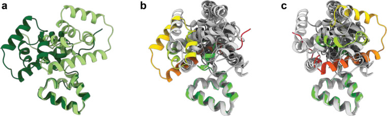
Extended Data Figure 9. Overlays of the FliGC/FliGM packing with prior crystal structures reveals the arrangement seen in both C-ring assemblies is unique. a, The arrangement of the FliGC (residues 234–331) differs by a rotation of 180° between the CCW (light green) and CW (dark green) structures relative to FliGM (residues 198–233 shown at bottom of panels and used to generate overlays). b-c,Previous crystal structures of FliGC/FliGM have revealed a variety of different arrangements between the domains. Earlier crystal structures (PDB ids 3ajc, 1lkv, 3usw and 3usy (two chains independently overlaid)) were overlaid onto the CCW (panel b) and CW (panel c) FliGM-198–233 using matchmaker within ChimeraX. None of the earlier crystal structures place the C subdomain in either position seen within the C-ring states.
Extended Data Figure 9. Overlays of the FliGC/FliGM packing with prior crystal structures reveals the arrangement seen in both C-ring assemblies is unique. a, The arrangement of the FliGC (residues 234–331) differs by a rotation of 180° between the CCW (light green) and CW (dark green) structures relative to FliGM (residues 198–233 shown at bottom of panels and used to generate overlays). b-c,Previous crystal structures of FliGC/FliGM have revealed a variety of different arrangements between the domains. Earlier crystal structures (PDB ids 3ajc, 1lkv, 3usw and 3usy (two chains independently overlaid)) were overlaid onto the CCW (panel b) and CW (panel c) FliGM-198–233 using matchmaker within ChimeraX. None of the earlier crystal structures place the C subdomain in either position seen within the C-ring states.CC BY · PubMed Central
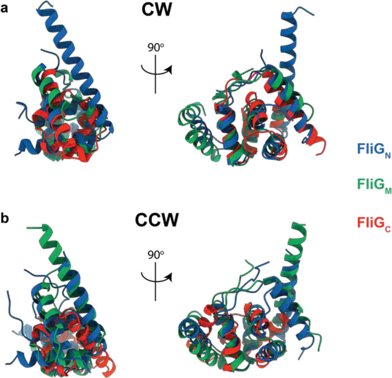
Extended Data Figure 10. The three FliG Domains assembled via inter-subunit domain swaps share a common architecture The compound FliGN, FliGM and FliGC domains assembled via inter-subunit domain swaps share the same domain architecture in both the CCW (a – R.M.S.D. 2.3 +/− 0.4 Å) and CW (b – R.M.S.D. 2.4 +/− 0.2 Å) states R.M.S.D. each domain onto all others, both states, 2.1 +/− 0.6 Å. Two views of the overlaid domains in a cartoon representation are shown for each state with the domains coloured as shown in the key.
Extended Data Figure 10. The three FliG Domains assembled via inter-subunit domain swaps share a common architecture The compound FliGN, FliGM and FliGC domains assembled via inter-subunit domain swaps share the same domain architecture in both the CCW (a – R.M.S.D. 2.3 +/− 0.4 Å) and CW (b – R.M.S.D. 2.4 +/− 0.2 Å) states R.M.S.D. each domain onto all others, both states, 2.1 +/− 0.6 Å. Two views of the overlaid domains in a cartoon representation are shown for each state with the domains coloured as shown in the key.CC BY · PubMed Central
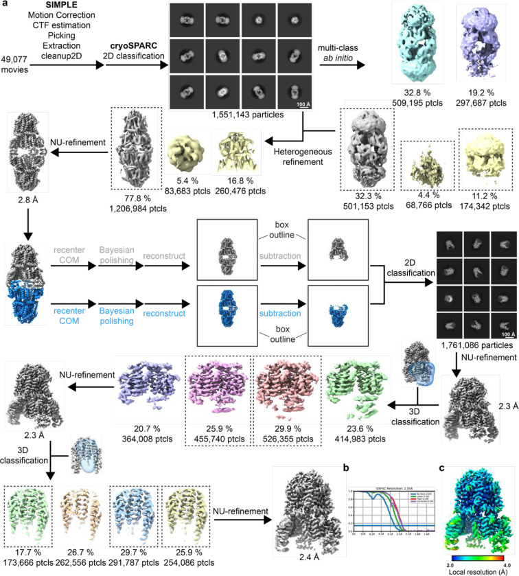
Extended Data Figure 11. Cryo-EM processing workflow, showing local and global map quality for MotAB + FliGc. a, Image processing workflow for MotAB + FliGc. b, Gold-standard FSC curves used for global-resolution estimates within cryoSPARC. c, Local-resolution estimation of reconstructed map as determined within cryoSPARC.
Extended Data Figure 11. Cryo-EM processing workflow, showing local and global map quality for MotAB + FliGc. a, Image processing workflow for MotAB + FliGc. b, Gold-standard FSC curves used for global-resolution estimates within cryoSPARC. c, Local-resolution estimation of reconstructed map as determined within cryoSPARC.CC BY · PubMed Central
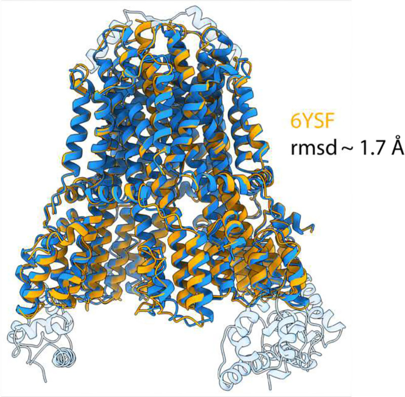
Extended Data Figure 12. Structural alignment of C. sporogenes MotAB with FliG-bound MotAB. C. sporogenes MotAB (PDB: 6YSF) superposed with FliG-bound MotAB structure presented in this study. MotAB shown in orange, FliG-bound MotAB shown blue. FliG and plug domains not modelled in 6YSF are transparent.
Extended Data Figure 12. Structural alignment of C. sporogenes MotAB with FliG-bound MotAB. C. sporogenes MotAB (PDB: 6YSF) superposed with FliG-bound MotAB structure presented in this study. MotAB shown in orange, FliG-bound MotAB shown blue. FliG and plug domains not modelled in 6YSF are transparent.CC BY · PubMed Central
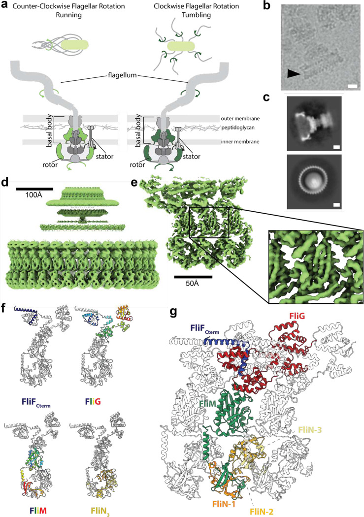
Figure 1. Structure of the Counter-Clockwise rotating state of the Salmonella Typhimurium flagellar C-ring. a, Upper panels: counter-clockwise (CCW) rotation of the Salmonella flagellum leads to flagellar bundling and coordinated movement whilst clockwise (CW) rotation leads to uncoordinated tumbling. Lower panels: cartoons of the flagellar assembly across the bacterial membranes highlighting in green (CCW light green, CW dark green) the location of the rotating structures (the rotor composed of the MS- and C-rings). b, Region of a cryoEM micrograph showing a flagellar basal body with intact C-ring in an approximately side on view (CCW state). Scale bar 100 Å. c, 2D class averages (CCW state) show both ‘side’ (upper panel) and top-down (lower panel) views. In the top-down view the 34 C-ring subunits can be counted. Scale bar 100 Å. d, 34-fold symmetrized cryoEM volume (light green) of the CCW locked flagellar rotor with alignments focused on the C-ring reveals the domain organization of the C-ring (lower density), and that the MS-ring is not aligned with the C-ring (blurred upper density). e, Using a mask around 3 subunits and refining symmetry expanded particles generates a higher resolution volume (3.2–4.5 Å across the subunit) for the central subunit allowing building and refinement of atomic models. f, A cartoon representation of a single subunit is shown highlighting the locations of the different protein chains. FliG and FliM are shown using rainbow coloring (blue at N-term to red at C-term), the cytoplasmic C-terminus of FliG in dark blue and the three copies of FliN in different shades of yellow. g, Cartoon representation of 3 subunits from a 34-mer C-ring. The central subunit is colored by protein chain with FliF and FliN colored as in (f) with FliG-red, FliM-green, the neighboring subunits in grey.
Figure 1. Structure of the Counter-Clockwise rotating state of the Salmonella Typhimurium flagellar C-ring. a, Upper panels: counter-clockwise (CCW) rotation of the Salmonella flagellum leads to flagellar bundling and coordinated movement whilst clockwise (CW) rotation leads to uncoordinated tumbling. Lower panels: cartoons of the flagellar assembly across the bacterial membranes highlighting in green (CCW light green, CW dark green) the location of the rotating structures (the rotor composed of the MS- and C-rings). b, Region of a cryoEM micrograph showing a flagellar basal body with intact C-ring in an approximately side on view (CCW state). Scale bar 100 Å. c, 2D class averages (CCW state) show both ‘side’ (upper panel) and top-down (lower panel) views. In the top-down view the 34 C-ring subunits can be counted. Scale bar 100 Å. d, 34-fold symmetrized cryoEM volume (light green) of the CCW locked flagellar rotor with alignments focused on the C-ring reveals the domain organization of the C-ring (lower density), and that the MS-ring is not aligned with the C-ring (blurred upper density). e, Using a mask around 3 subunits and refining symmetry expanded particles generates a higher resolution volume (3.2–4.5 Å across the subunit) for the central subunit allowing building and refinement of atomic models. f, A cartoon representation of a single subunit is shown highlighting the locations of the different protein chains. FliG and FliM are shown using rainbow coloring (blue at N-term to red at C-term), the cytoplasmic C-terminus of FliG in dark blue and the three copies of FliN in different shades of yellow. g, Cartoon representation of 3 subunits from a 34-mer C-ring. The central subunit is colored by protein chain with FliF and FliN colored as in (f) with FliG-red, FliM-green, the neighboring subunits in grey.CC BY · PubMed Central
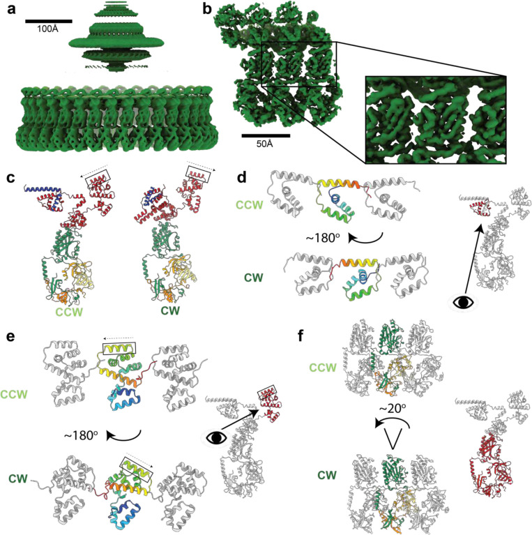
Figure 2. Structure of the Clockwise rotating state of the Salmonella typhimurium flagellar C-ring and large domain rearrangements between the CCW and CW states. a, 34-fold symmetrized cryoEM volume (dark green) of the CW locked flagellar rotor with alignments focused on the C-ring reveals, as shown for in Figure 1d for the CCW state, the domain organization of the C-ring (lower density), and that the MS-ring is not aligned with the C-ring (blurred upper density). b, Using a mask around 3 subunits and refining symmetry expanded particles generates a higher resolution volume (3.3–5.2 Å across the subunit) for the central subunit allowing building and refinement of atomic models. c, A cartoon representation of single subunits colored as in Figure 1g shows the dramatic changes in domain arrangements between the CCW and CW states. The FliGC torque helix is boxed and the arrow indicates the N-C direction. d-f highlight the dramatic domain rearrangements domain by domain for the subunit regions indicated in red on the cartoon of the single full subunit in each panel. The domains are shown in context of the 3-subunits with the CCW state above and the CW state below (central subunit domain color - rainbow (d,e); by chain as in c (f)). (d,e) The eye and arrow show the approximate view point from which the CCW/CW domains are viewed, (f) view is as for the small, full subunit.
Figure 2. Structure of the Clockwise rotating state of the Salmonella typhimurium flagellar C-ring and large domain rearrangements between the CCW and CW states. a, 34-fold symmetrized cryoEM volume (dark green) of the CW locked flagellar rotor with alignments focused on the C-ring reveals, as shown for in Figure 1d for the CCW state, the domain organization of the C-ring (lower density), and that the MS-ring is not aligned with the C-ring (blurred upper density). b, Using a mask around 3 subunits and refining symmetry expanded particles generates a higher resolution volume (3.3–5.2 Å across the subunit) for the central subunit allowing building and refinement of atomic models. c, A cartoon representation of single subunits colored as in Figure 1g shows the dramatic changes in domain arrangements between the CCW and CW states. The FliGC torque helix is boxed and the arrow indicates the N-C direction. d-f highlight the dramatic domain rearrangements domain by domain for the subunit regions indicated in red on the cartoon of the single full subunit in each panel. The domains are shown in context of the 3-subunits with the CCW state above and the CW state below (central subunit domain color - rainbow (d,e); by chain as in c (f)). (d,e) The eye and arrow show the approximate view point from which the CCW/CW domains are viewed, (f) view is as for the small, full subunit.CC BY · PubMed Central
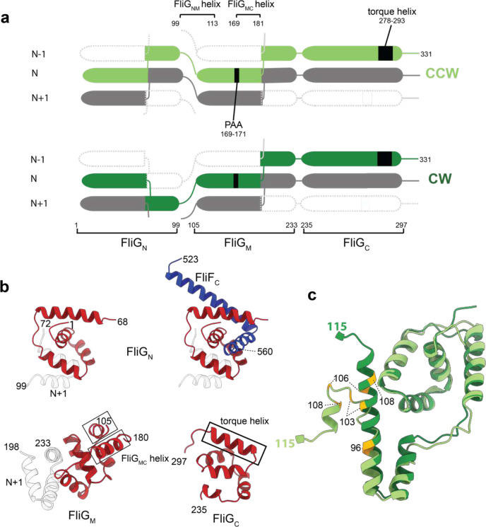
Figure 3. Both FliGN and FliGM domains are completed via inter-subunit domain swaps but FliGN inverts which subunit contributes the C-terminal portion of the fold in the CCW and CW states. a, domain swapping within FliG is shown with residue boundaries and key features discussed in text indicated for both CCW (upper) and CW (lower) states. b, Each FliG domain is shown with the N-subunit derived sequence shown in red and the N+1 in grey for the CW state. FliGN is shown twice in the upper half of the panel with FliG residues on the left-hand side and including the FliFC that folds with these sequences to complete the domain on the right-hand side. c, Resdiues 1–115 of FliG are shown in CCW (light green) and CW (dark green) states. Residues that introduce a strong clockwise bias are colored yellow.
Figure 3. Both FliGN and FliGM domains are completed via inter-subunit domain swaps but FliGN inverts which subunit contributes the C-terminal portion of the fold in the CCW and CW states. a, domain swapping within FliG is shown with residue boundaries and key features discussed in text indicated for both CCW (upper) and CW (lower) states. b, Each FliG domain is shown with the N-subunit derived sequence shown in red and the N+1 in grey for the CW state. FliGN is shown twice in the upper half of the panel with FliG residues on the left-hand side and including the FliFC that folds with these sequences to complete the domain on the right-hand side. c, Resdiues 1–115 of FliG are shown in CCW (light green) and CW (dark green) states. Residues that introduce a strong clockwise bias are colored yellow.CC BY · PubMed Central
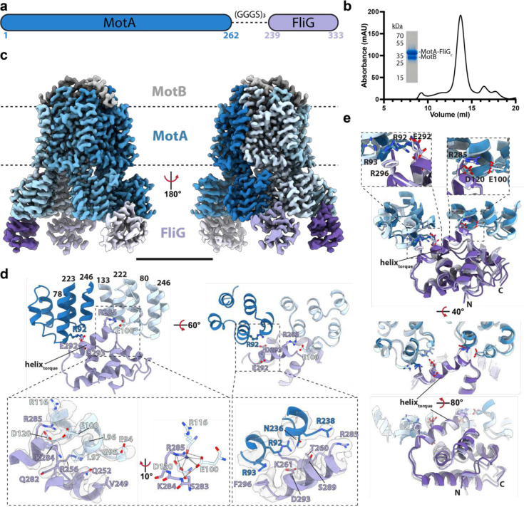
Figure 4. Design, purification, and cryo-EM structure of a stator complex bound to FliGc. a, Schematic of the Clostridium sporogenes MotA-FliG fusion construct used in this study. b, Size-exclusion chromatogram of MotAB-FliGc complex with corresponding SDS-PAGE gel. c, Cryo-EM volume of MotAB-FliGc complex. Volume for MotA, MotB and FliGc subunits are depicted in various shades of blue, grey, and purple, respectively. The membrane, assigned from the position of the detergent micelle, is depicted by the dashed line. Scale bar is 50 Å. d, Modeling of a MotA-FliG interface. Cytoplasmic MotA extensions are shown in dark and light blue, and FliGc is shown in purple. H-bonds are depicted as dashed lines. Cryo-EM density displayed as transparent surface. e, Structural alignment of the FliGc torque helix across all bound FliGc subunits. Subunit coloring consistent with panels b and c. Residues depicted in this figure are based on C. sporogenes annotation. See Table S1 for species equivalence in E. coli or S. typhimurium.
Figure 4. Design, purification, and cryo-EM structure of a stator complex bound to FliGc. a, Schematic of the Clostridium sporogenes MotA-FliG fusion construct used in this study. b, Size-exclusion chromatogram of MotAB-FliGc complex with corresponding SDS-PAGE gel. c, Cryo-EM volume of MotAB-FliGc complex. Volume for MotA, MotB and FliGc subunits are depicted in various shades of blue, grey, and purple, respectively. The membrane, assigned from the position of the detergent micelle, is depicted by the dashed line. Scale bar is 50 Å. d, Modeling of a MotA-FliG interface. Cytoplasmic MotA extensions are shown in dark and light blue, and FliGc is shown in purple. H-bonds are depicted as dashed lines. Cryo-EM density displayed as transparent surface. e, Structural alignment of the FliGc torque helix across all bound FliGc subunits. Subunit coloring consistent with panels b and c. Residues depicted in this figure are based on C. sporogenes annotation. See Table S1 for species equivalence in E. coli or S. typhimurium.CC BY · PubMed Central
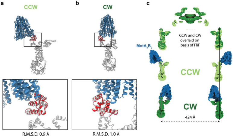
Figure 5. Overlaying MotA5B2-FliG on the CCW and CW C-rings reveals the stator complex switches from outside the C-ring to inside it. a,b The MotA5B2-FliG complex is overlaid on the same FliGC domain with the CCW (a) and CW (b) C-ring subunits. The zoom box shows that the FliGC domain is not structurally altered in the context of the C-ring subunit and overlays well, however, the rotation of the FliGC domain in the context of the different rotational states results in the MotA5B2 complex being presented on the external (CCW) or internal (CW) face of the C-ring. c, Aligning the CCW and CW structures based on the invariant FliF component of the rotor reveals that (i) the Salmonella C-ring does not change diameter as part of switching and (upper panel shows the overlaid volumes with CCW – light green and CW – dark green (ii) The lower two panels show the MotA5B2-FliGc complex in the context of the CCW and CW C-rings further illustrating that the stators move from pushing the C-ring on the outside to the inside of the C-ring. Thus explaining how a stator that rotates in a single direction can power bi-directional movement of the C-ring
Figure 5. Overlaying MotA5B2-FliG on the CCW and CW C-rings reveals the stator complex switches from outside the C-ring to inside it. a,b The MotA5B2-FliG complex is overlaid on the same FliGC domain with the CCW (a) and CW (b) C-ring subunits. The zoom box shows that the FliGC domain is not structurally altered in the context of the C-ring subunit and overlays well, however, the rotation of the FliGC domain in the context of the different rotational states results in the MotA5B2 complex being presented on the external (CCW) or internal (CW) face of the C-ring. c, Aligning the CCW and CW structures based on the invariant FliF component of the rotor reveals that (i) the Salmonella C-ring does not change diameter as part of switching and (upper panel shows the overlaid volumes with CCW – light green and CW – dark green (ii) The lower two panels show the MotA5B2-FliGc complex in the context of the CCW and CW C-rings further illustrating that the stators move from pushing the C-ring on the outside to the inside of the C-ring. Thus explaining how a stator that rotates in a single direction can power bi-directional movement of the C-ringCC BY · PubMed Central
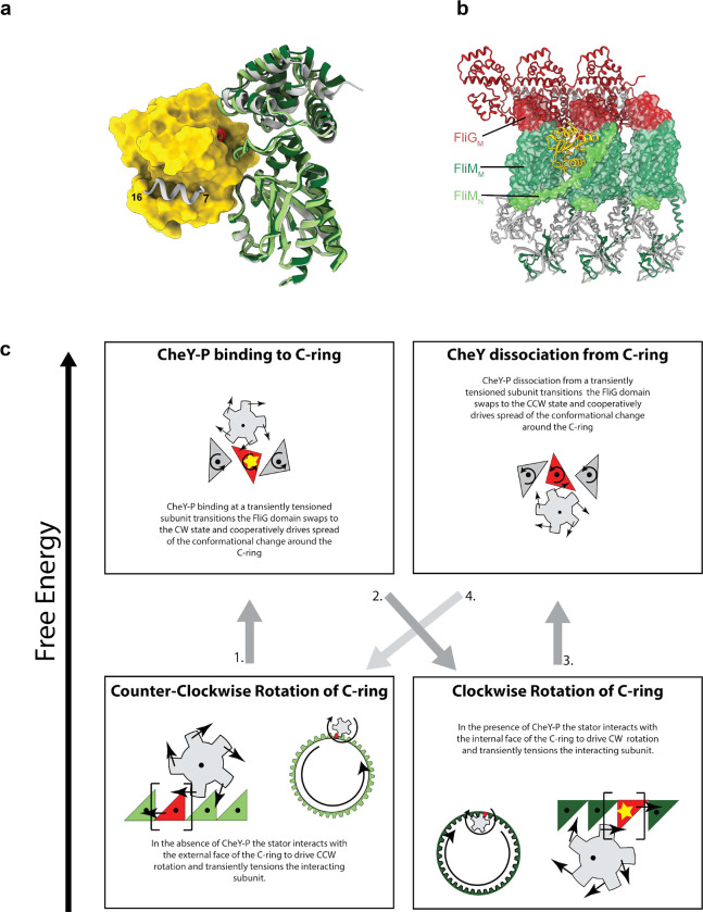
Figure 6. Mechanism for switching based on structures for CCW and CW flagellar C-rings a, Using AlphaFold2 to predict the interactions between CheY-P (yellow surface, phosphate shown as space filling atoms)and the C-ring (silver cartoon) generates an arrangement of the FliMM/FliGM domains that matches that seen in the CW state (dark green) but not the CCW state (light green, overlaid based on FliMM to highlight relative movement of FliGM). The previously determined interaction between the FliM N-terminus (silver helix on CheY-P surface) and CheY-P is highlighted. b, Mapping the location of CheY-P and the full N-terminus of FliM from the AlphaFold model to a set of three neighboring CW subunits reveals the nestling of CheY-P into the C-ring at a subunit-subunit interface and with interactions spread across two subunits. c, Schematic illustrating the mechanistic implications of our structures and models for how the uni-directional stators drive bi-directional rotation and its control by CheY-P binding.
Figure 6. Mechanism for switching based on structures for CCW and CW flagellar C-rings a, Using AlphaFold2 to predict the interactions between CheY-P (yellow surface, phosphate shown as space filling atoms)and the C-ring (silver cartoon) generates an arrangement of the FliMM/FliGM domains that matches that seen in the CW state (dark green) but not the CCW state (light green, overlaid based on FliMM to highlight relative movement of FliGM). The previously determined interaction between the FliM N-terminus (silver helix on CheY-P surface) and CheY-P is highlighted. b, Mapping the location of CheY-P and the full N-terminus of FliM from the AlphaFold model to a set of three neighboring CW subunits reveals the nestling of CheY-P into the C-ring at a subunit-subunit interface and with interactions spread across two subunits. c, Schematic illustrating the mechanistic implications of our structures and models for how the uni-directional stators drive bi-directional rotation and its control by CheY-P binding.CC BY · PubMed Central

Verification

Claims the paper makes

The claims and statistics of this paper haven’t been checked yet.

Run the check — free, no account needed. It reads the open-access text and checks the sources it cites.

A few free checks a day · papers already verified open instantly · results are public

Self-check

Percentages, sums and reported differences re-computed from the paper’s own numbers.

The self-check needs the paper’s full text.

Citations

Cites

Metadata

Authors
Lea, S., Johnson, S., Deme, J., Furlong, E., Chevance, F., Hughes, K., & Caesar, J.
Affiliations
  • National Cancer Institute (US)
  • Australian National University (AU)
  • University of Utah (US)
  • University of Oxford (GB)
Corresponding author
  • Lea, Susan
  • Johnson, Steven
Venue
Nature Microbiology
Published
2023-10-23
Volume
9
Issue
5
Pages
1282-1292
ISSN
2058-5276 (ISSN-L)
OpenAlex
W4392581886
Cited by
60
References
1
Citations by year
2026: 15 · 2025: 27 · 2024: 18
FWCI
15.87
Type
journal article
Language
en
Open access
Locations
  • Nature Microbiology (publishedVersion)
  • Research Square (acceptedVersion, cc-by)
  • PubMed (publishedVersion)
  • PubMed Central (submittedVersion, cc-by)
Funders
  • U.S. Department of Health and Human Services
  • Wellcome Trust (201536, 219477/Z/19/Z, 209194, 219477)
  • Wolfson Foundation (WL160052)
  • National Institutes of Health
  • Medical Research Council (S021264)
  • National Cancer Institute
  • National Institute of General Medical Sciences (R01GM056141)
Topics
  • Life Sciences › Biochemistry, Genetics and Molecular Biology › Genetics › Bacterial Genetics and Biotechnology
  • Life Sciences › Biochemistry, Genetics and Molecular Biology › Structural Biology › Advanced Electron Microscopy Techniques and Applications
  • Life Sciences › Biochemistry, Genetics and Molecular Biology › Molecular Biology › ATP Synthase and ATPases Research
Keywords
bacterial flagellum, flagellar basal body, FliG, C ring, Salmonella typhimurium, chemotaxis, cryo-EM structure
MeSH terms
Bacterial Proteins, Flagella, Models, Molecular, Protein Conformation, Rotation, Salmonella, Salmonella typhimurium, Cryoelectron Microscopy, Basal Bodies

About these checks

Registry, retraction, Cites and statistics results are computed, not judged, with one exception: a printed reference that no index lists is read once by a model before it counts as a citation error. Claims are extracted by a model and kept only when their quote appears verbatim in the text; each cited source is then checked, with a model’s help, for whether it says what the claim relies on. Those verdicts can be wrong — read the claim’s quote and the cited source before relying on one.

Statistics and arithmetic are recomputed, not judged.

Confidence bands are shown only for fields calibrated on our annotated test set. None is calibrated yet, so no band is shown.

What counts as a claim ›How we measure confidence ›How we check this ›

Are you an author, or do you see a problem with this page? Request a review