

The DOI matches its Crossref record.
An Effective Switching Algorithm for Single Phase Matrix Converter in Induction Heating Applications
Abstract
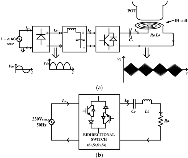
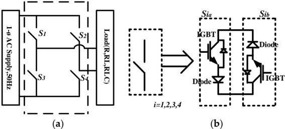
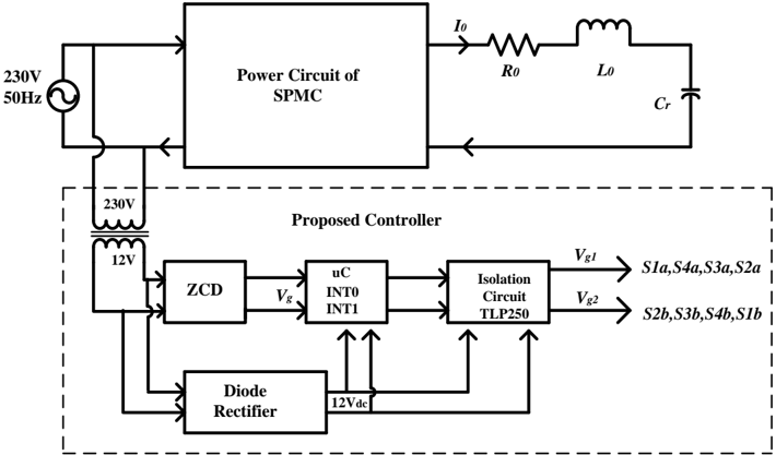
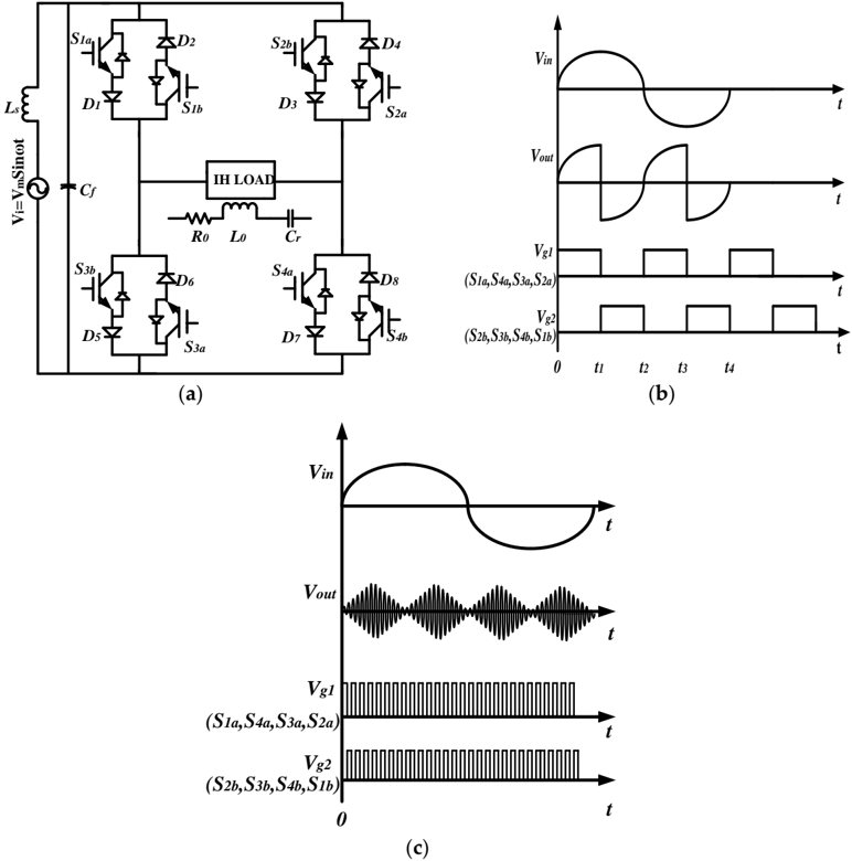
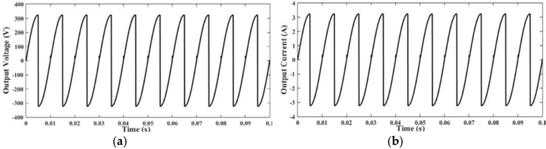
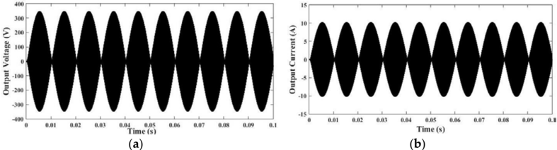
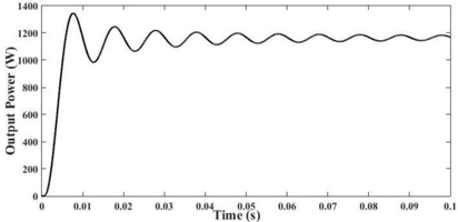
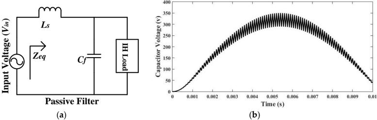
Prevalent converters for induction heating (IH) applications employ two-stage conversion for generating high-frequency magnetic field, namely, AC to DC and then DC to high-frequency AC (HFAC). This research embarks upon a direct conversion of utility AC to high frequency AC with the design of a single-phase matrix converter (SPMC) as a resonant converter using a modified switching technique for IH application. The efficacy of the proposed approach is validated through different attributes such as unity power factor, sinusoidal input current and low total harmonic distortion (THD). The developed prototype-embedded system has high pragmatic deployment potential owing to its cost effectiveness using Arduino mega 2560 and high voltage/current as well as low switching time IXRH40N120 insulated-gate bipolar transistor (IGBT). Different results of the prototype-embedded system for IH application have been verified using Matlab Simulink environment to corroborate its efficacy.
Overview
The claims and statistics of this paper haven’t been checked yet.
Run the check — free, no account needed. It reads the open-access text and checks the sources it cites.
Integrity signals
Registry
Cites
Statistics
Figures
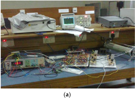
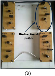
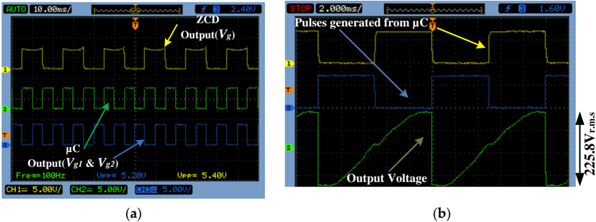
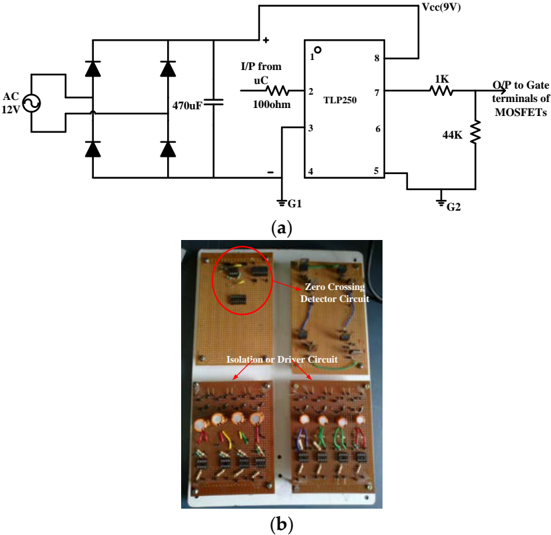
Verification
Claims the paper makes
The claims and statistics of this paper haven’t been checked yet.
Run the check — free, no account needed. It reads the open-access text and checks the sources it cites.
Claims other papers make about this one
Each is checked against this paper’s own text: does it say what the citing paper says it does?
In the citing paper
“A converter structure with proven application in induction heating, giving high power density and the ability to operate with soft-switching, is the full-bridge circuit with a parallel or series resonant tank, based on different modulation techniques, such as Phase-Shift Modulation (PSM), Pulse-Frequency Modulation (PFM), Pulse-Density Modulation (PDM) and Asymmetrical Duty-Cycle (ADC) [25][26][27”
In the citing paper
“induction heating inverters, with an installed power higher than 10-15 kW for industrial and laboratory research purposes [29][30][31], can be constructed by IGBT transistors connected in parallel”
Self-check
Percentages, sums and reported differences re-computed from the paper’s own numbers.
The self-check needs the paper’s full text.
Citations
Cites
No references could be resolved yet.
Research works printed but not linked: 36
- Acero, 2010, Domestic induction appliances, IEEE Ind. Appl. Mag., 16, 39, 10.1109/MIAS.2009.935495 · DOI
- Sarnago, 2013, Modulation scheme for improved operation of an RB-IGBT-based resonant inverter applied to domestic induction heating, IEEE Trans. Ind. Electron., 60, 2066, 10.1109/TIE.2012.2207652 · DOI
- Sarnago, 2013, Class-D/DE dual-mode-operation resonant converter for improved-efficiency domestic induction heating system, IEEE Trans. Power Electron., 28, 1274, 10.1109/TPEL.2012.2206405 · DOI
- Lucia, 2009, Load-adaptive control algorithm of half-bridge series resonant inverter for domestic induction heating, IEEE Trans. Ind. Electron., 56, 3106, 10.1109/TIE.2009.2022516 · DOI
- Maussion, 2011, Induction heating technology and its applications: Past Developments, current Technology, and future challenges, IEEE Trans. Ind. Electron., 61, 2509
- Mishima, 2014, A new current phasor-controlled ZVS twin half-bridge high-frequency resonant inverter for induction heating, IEEE Trans. Ind. Electron., 61, 2531, 10.1109/TIE.2013.2274420 · DOI
- Saha, 2014, High Power Density Series Resonant Inverter Using an Auxiliary Switched Capacitor Cell for Induction Heating Applications, IEEE Trans. Power Electron., 29, 1909, 10.1109/TPEL.2013.2265984 · DOI
- Acero, 2010, Efficiency-oriented design of ZVS half-bridge series resonant inverter with variable frequency duty cycle control, IEEE Trans. Power Electron., 25, 1671, 10.1109/TPEL.2010.2042461 · DOI
- Sarnago, 2016, Dual-Output Boost Resonant Full-Bridge Topology and its Modulation Strategies for High-Performance Induction Heating Applications, IEEE Trans. Ind. Electron., 63, 3554, 10.1109/TIE.2016.2530780 · DOI
- Singh, B., and Pandey, R. (2016, January 4–6). Improved Power Quality Buck-Boost Converter fed LLC Resonant Converter for Induction Heater. Proceedings of the 2016 IEEE 6th International Conference on Power Systems (ICPS), New Delhi, India. · DOI
- Pham, H., Fujita, H., Ozaki, K., and Uchida, N. (2011, January 17–22). Dynamic analysis and control of a zone-control induction heating system. Proceedings of the 2011 IEEE conference of Energy Conversion Congress and Exposition(ECCE), Phoenix, AZ, USA.
- Fujita, 1996, Pulse-Density-Modulated Power Control of a 4 kW, 450 kHz Voltage-Source Inverter for Induction Melting Applications, IEEE Trans. Ind. Appl., 32, 279, 10.1109/28.491475 · DOI
- Grajales, L., Sabatk, J.A., Wang, K.R., Tabisz, W.A., and Lee, F.C. (1993, January 2–8). Design of a 10 kW, 500 kHz Phase-Shift Controlled Series-Resonant Inverter for Induction Heating. Proceedings of the 1993 IEEE Industry Applications Conference Twenty-Eighth IAS Annual Meeting, Toronto, ON, Canada.
- Yilmaz, 2012, Medium-frequency induction melting furnace as a load on the power system, IEEE Trans. Ind. Appl., 48, 1203, 10.1109/TIA.2012.2199457 · DOI
- Millan, 2011, Series resonant inverter with selective harmonic operation applied to all-metal domestic induction heating, IET Power Electron., 4, 587, 10.1049/iet-pel.2010.0107 · DOI
- Koertzen, H.W., Van Wyk, J.D., and Ferreira, J.A. (1995, January 18–22). Design of the half-bridge series resonant converters for induction cooking. Proceedings of the Power Electronics Specialist Conference (PESC), Atlanta, GA, USA.
- Dawson, 1991, A Comparison of Load Commutated Inverter Systems for Induction Heating and Melting Applications, IEEE Trans. Power Electron., 6, 430, 10.1109/63.85911 · DOI
- Koertzen, H.W., Ferreira, J.A., and Van Wyk, J.D. (July, January 29). A comparative study of single switch induction heating converters using novel component effectivity concepts. Proceedings of the 23rd Annual IEEE Power Electronics Specialists Conference (PESC), Toledo, Spain.
- Jimenez, 2014, An FPGA-based gain-scheduled controller for resonant converters applied to induction cooktops, IEEE Trans. Power Electron., 29, 2143, 10.1109/TPEL.2013.2276041 · DOI
- Nagarajan, 2015, Phase locked loop based pulse density modulation scheme for the power control of induction heating applications, J. Power Electron., 15, 65, 10.6113/JPE.2015.15.1.65 · DOI · Paper page
- Idris, Z., Hamzah, M.K., and Saidon, M.F. (2006, January 18–22). Implementation of single-phase matrix converter as a direct AC–AC converter with commutation strategies. Proceedings of the 2006 37th IEEE Power Electronics Specialists Conference, Jeju, South Korea. · DOI
- Li, 2012, A direct AC–AC converter for inductive power-transfer systems, IEEE Trans. Power Electron., 27, 661, 10.1109/TPEL.2011.2159397 · DOI
- Arevalo, 2010, Control and implementation of a matrix-converter-based AC ground power-supply unit for aircraft servicing, IEEE Trans. Ind. Electron., 57, 2076, 10.1109/TIE.2009.2034180 · DOI
- Kolar, 2007, Novel three-Phase AC–AC sparse matrix converters, IEEE Trans. Power Electron., 22, 1649, 10.1109/TPEL.2007.904178 · DOI
- Trentin, 2012, Automated optimal design of input filters for direct ac/ac matrix converters, IEEE Trans. Ind. Electron., 59, 2811, 10.1109/TIE.2011.2163283 · DOI
- Yamamoto, 2011, Development of MCs and its applications in industry, IEEE Ind. Electron. Mag., 5, 4, 10.1109/MIE.2011.940249 · DOI
- Hosseini, S.H., Sharifian, M.B., Sabahi, M., Yazdanpanah, A., and Gharehpetian, G.H. (2008, January 4–7). Bi-directional power electronic transformer for induction heating systems. Proceedings of the 2008 Canadian Conference on Electrical and Computer Engineering, Niagara Falls, ON, Canada. · DOI
- Kim, 1988, Characteristics and Starting Method of a Cycloconverter With a Tank Circuit for Induction Heating, IEEE Trans. Power Electron., 3, 236, 10.1109/63.4354 · DOI
- Sugimura, H., Mun, S.P., Kwon, S.K., Mishima, T., and Nakaoka, M. (July, January 30). Direct AC–AC resonant converter using one-chip reverse blocking IGBT-Based bidirectional switches for HF induction heaters. Proceedings of the 2008 IEEE International Symposium on Industrial Electronics, Cambridge, UK.
- Salehifar, M., Moreno-eguilaz, M., Sala, V., and Romeral, L. (2013, January 17–21). A Novel AC–AC Converter Based SiC for Domestic Induction Cooking Applications. Proceedings of the 2013 28th Twenty-Eighth Annual IEEE Applied Power Electronics Conference and Exposition (APEC), Long Beach, CA, USA. · DOI
- Nguyen-Quang, N., Stone, D.A., Bingham, C.M., and Foster, M.P. (2006, January 23–26). Single phase matrix converter for radio frequency induction heating. Proceedings of the International Symposium on Power Electronics, Electrical Drives, Automation and Motion (SPEEDAM), Taormina, Italy.
- Mohite, S.B., and Gujarathi, P.K. (2010, January 14–16). A Design and Implementation of a Novel Multimode Single Phase Matrix Converter. Proceedings of the 2010 IEEE Power Electronics Electrical Drives Automation and Motion SPEEDAM, Pisa, Italy. · DOI
- Nguyen-Quang, N., Stone, D.A., Bingham, C.M., and Foster, M.P. (2009, January 8–10). A three-phase to single-phase matrix converter for high-frequency induction heating. Proceedings of the 2009 13th European Conference on Power Electronics and Applications, Barcelona, Spain.
- Nguyen-Quang, N., Stone, D.A., Bingham, C.M., and Foster, M.P. (2007, January 2–5). Comparison of single-phase matrix converter and H-bridge converter for radio frequency induction heating. Proceedings of the 2007 European Conference on Power Electronics and Applications, Aalborg, Denmark. · DOI
- Jose, P.S., Deepika, N.C., and Nisha, S.N. (2011, January 23–24). Applications of single phase matrix converter. Proceedings of the 2011 International Conference on Emerging Trends in Electrical and Computer Technology, Nagercoil, India. · DOI
- Kumar, 2011, A Survey on High-Frequency Inverter and Their Power Control Techniques for Induction Heating Applications, J. Power Technol., 97, 201
Cited by
Dimitrov, B., Hayatleh, K., Barker, S., & Collier, G. (2021) · Electricity · doi:10.3390/electricity2040026 · Cited by 3
Metadata
- Authors
- Kumar, A., Kumar Sadhu, P., Kumar Mohanta, D., & Bharata Reddy, M. J.
- Venue
- Electronics
- Publisher
- MDPI AG
- Published
- 2018-08-18
- Volume
- 7
- Issue
- 8
- Pages
- 149
- ISSN
- 2079-9292
- Cited by
- 21
- References
- 0
- Language
- en
About these checks
Registry, retraction, Cites and statistics results are computed, not judged, with one exception: a printed reference that no index lists is read once by a model before it counts as a citation error. Claims are extracted by a model and kept only when their quote appears verbatim in the text; each cited source is then checked, with a model’s help, for whether it says what the claim relies on. Those verdicts can be wrong — read the claim’s quote and the cited source before relying on one.
Statistics and arithmetic are recomputed, not judged.
Confidence bands are shown only for fields calibrated on our annotated test set. None is calibrated yet, so no band is shown.
What counts as a claim ›How we measure confidence ›How we check this ›
Are you an author, or do you see a problem with this page? Request a review
Data sources
Bibliographic data: Semantic Scholar, OpenAlex, Crossref.
Contains information from the Semantic Scholar Academic Graph Datasets, made available under the ODC Attribution License (ODC-BY 1.0).
Semantic Scholar’s data is described in: Kinney, R., et al. (2023). The Semantic Scholar Open Data Platform. arXiv:2301.10140.
