

The DOI matches its Crossref record; 25 of the 27 references it cites were found in a registry or an index.
A Broad Dual-Band Implantable Antenna for RF Energy Harvesting and Data Transmitting
Open accessAbstract
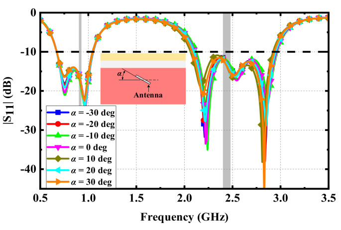
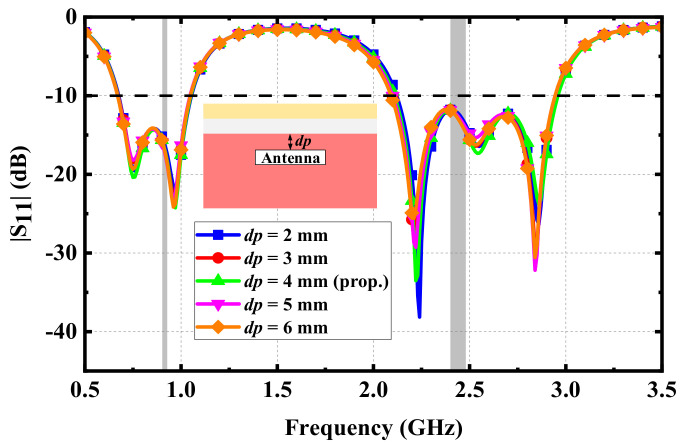
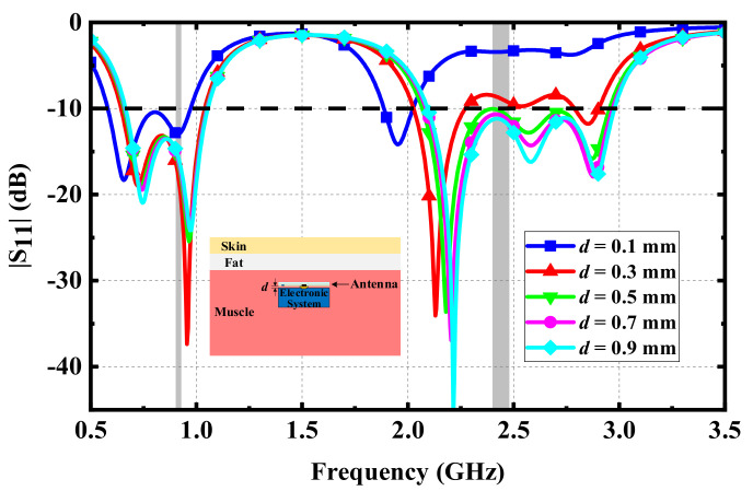
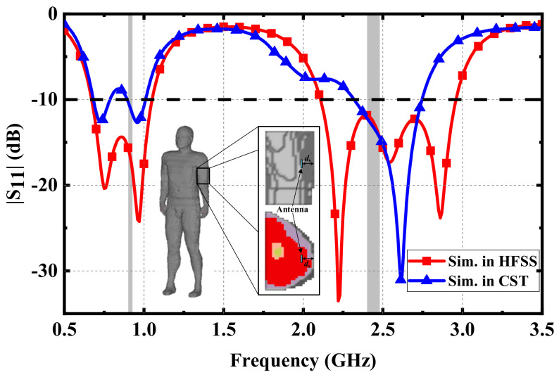
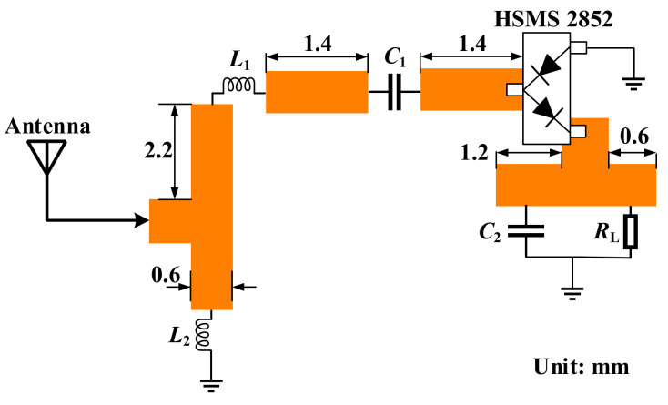
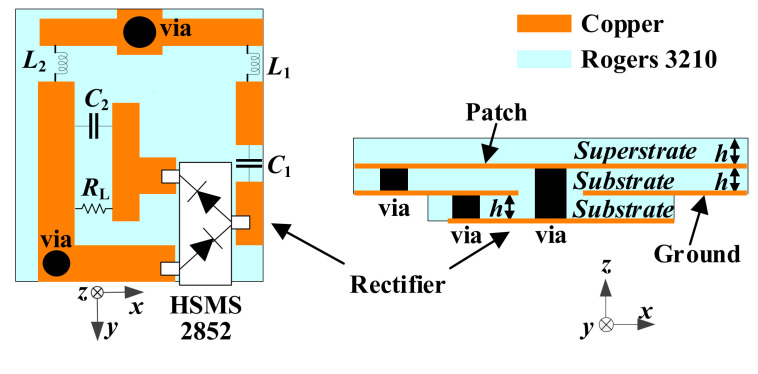
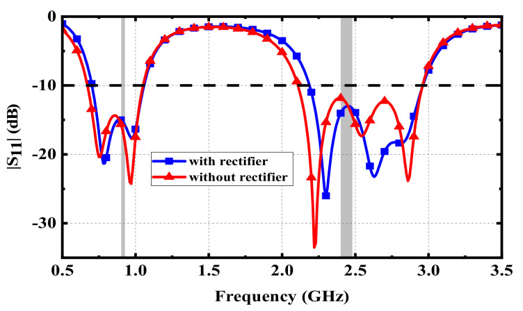
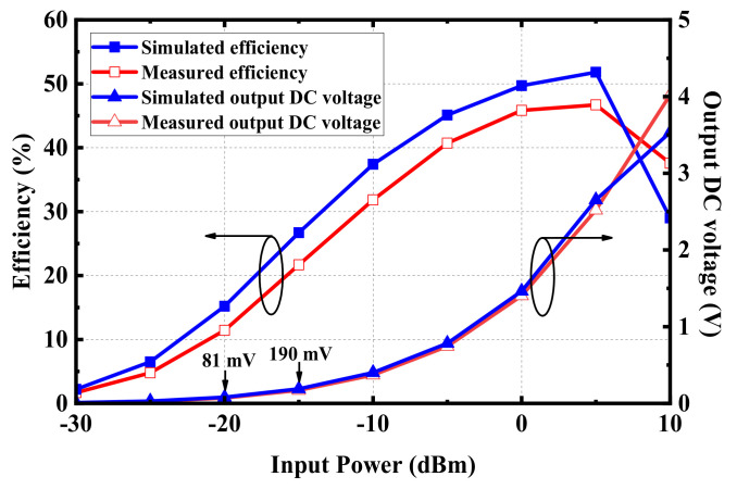
An implantable antenna, operating at the dual Industrial, Scientific, and Medical (ISM) bands of 902–928 MHz and 2.4–2.48 GHz, is presented for RF energy harvesting and data transmission. By introducing multiple radiating branches and etching a C-shaped slot, multiple resonant frequencies were generated to produce the wide dual bands. The proposed antenna has compact dimensions of 7.9 × 7.7 × 1.27 mm3. The simulated impedance bandwidths of the antenna are 0.67–1.05 GHz (44.2%) and 2.11–2.96 GHz (33.5%), and the peak gains are −28.9 dBi and −29.5 dBi, respectively. The lower band can be applied in RF energy harvesting, while the upper band is designed for data transmission with external medical equipment. Furthermore, to convert RF power into DC power, in RF energy harvesting, a voltage-doubled rectifier was positioned under the ground plane of the proposed antenna. The rectifier circuit can achieve a maximum conversion efficiency of 52% at an input power of 5 dBm. Furthermore, the integrated scheme of the implantable rectenna was fabricated and the numerical performance of the wireless power transfer was verified with the measurement results.
Overview
The claims and statistics of this paper haven’t been checked yet.
Run the check — free, no account needed. It reads the open-access text and checks the sources it cites.
Integrity signals
Registry
Cites
Statistics
Figures
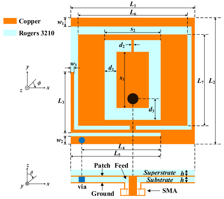
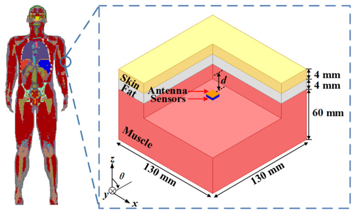
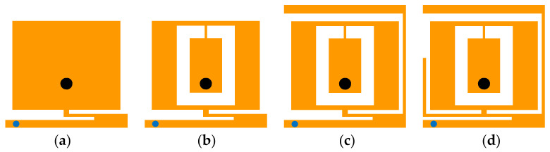
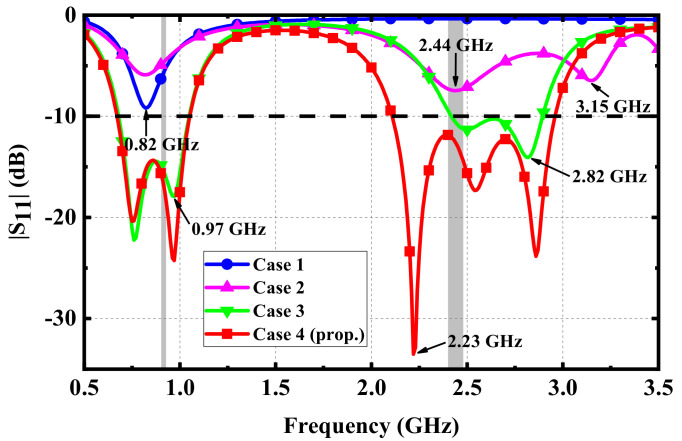
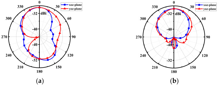
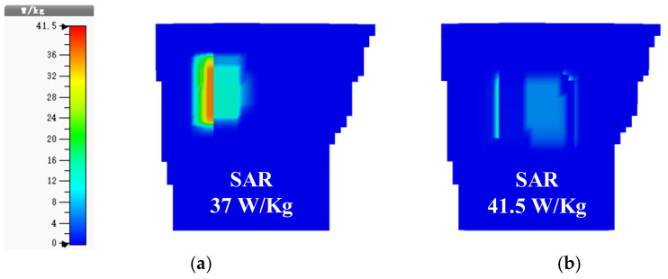
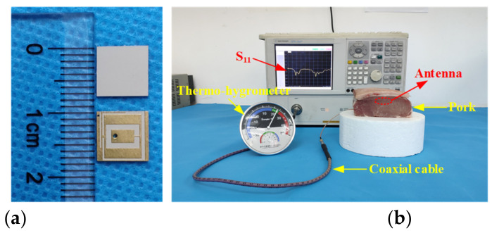
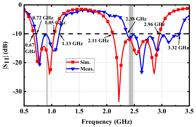
Verification
Claims the paper makes
The claims and statistics of this paper haven’t been checked yet.
Run the check — free, no account needed. It reads the open-access text and checks the sources it cites.
Claims other papers make about this one
Each is checked against this paper’s own text: does it say what the citing paper says it does?
The source backs part of the claim, not all of it — or backs it for a different population, condition or comparison.
In the citing paper
“This dispersion of energy means that only a fraction of the transmitted power is captured by the receiver, necessitating higher power outputs from the transmitter to ensure adequate energy reaches the implant.”
From Comparative analysis of energy transfer mechanisms for neural implants (2024) · cites this paper as Fan et al., 2022
Experimental — accuracy not yet measuredThe source backs part of the claim, not all of it — or backs it for a different population, condition or comparison.
In the citing paper
“However brain implants require minimization of the system to reduce the invasiveness of the procedure which might conflict with the ideal antenna size needed for efficient RF energy transfer, leading to a trade-off between the physical size of the implant and the efficiency of power reception (Ferguson and Redish, 2011; Di Carlo et al., 2018; Fan et al., 2022).”
From Comparative analysis of energy transfer mechanisms for neural implants (2024) · cites this paper as Fan et al., 2022
Experimental — accuracy not yet measuredThe cited source says what the claim attributes to it.
In the citing paper
“This increase in power output can, in turn, lead to heightened concerns about tissue heating (Di Carlo et al., 2018; Fan et al., 2022; Guo et al., 2022).”
From Comparative analysis of energy transfer mechanisms for neural implants (2024) · cites this paper as Fan et al., 2022
The cited source says what the claim attributes to it.
In the citing paper
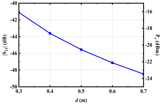
“As the distance between the transmitter and receiver increases, the power transfer efficiency typically decreases due to the spreading of electromagnetic waves.”
From Comparative analysis of energy transfer mechanisms for neural implants (2024) · cites this paper as Fan et al., 2022
Self-check
Percentages, sums and reported differences re-computed from the paper’s own numbers.
The self-check needs the paper’s full text.
Citations
Cites
Gabriel, S., Lau, R.-W.-M., & Gabriel, C. (1996) · Physics in Medicine and Biology · doi:10.1088/0031-9155/41/11/002 · Cited by 4,487 · cited 1×
“In the simulation of the dual-band antenna, the dielectric properties of human tissues, such as relative permittivity and loss tangent, should be set as the values at the center frequency in the two target bands [25].”
BackgroundA Leadless Intracardiac Transcatheter Pacing System
REYNOLDS, D. W., Duray, G. Z., Omar, R., Soejima, K., Neužil, P., Zhang, S., Narasimhan, C., Steinwender, C., Brugada, J., Lloyd, M. S., et al. (2015) · New England Journal of Medicine · doi:10.1056/nejmoa1511643 · Cited by 935 · cited 1×
“These IMDs include blood pressure monitors [2], cochlear implants [3], and implantable pacemakers [4], and others.”
BackgroundWireless Power Transfer Strategies for Implantable Bioelectronics
Agarwal, K., Jegadeesan, R., Guo, Y., & Thakor, N. V. (2017) · IEEE Reviews in Biomedical Engineering · doi:10.1109/rbme.2017.2683520 · Cited by 549 · cited 1×
“To address the above issues, wireless power transfer (WPT) technology in medical systems can be adopted [7].”
BackgroundPower Approaches for Implantable Medical Devices
Amar, A. B., Kouki, A. B., & Cao, H. (2015) · Sensors · doi:10.3390/s151128889 · Cited by 445 · cited 1×
“However, the working lives of IMDs are limited by their batteries [5,6].”
BackgroundLiu, C.-R., Guo, Y.-X., & Xiao, S. (2014) · IEEE Transactions on Antennas and Propagation · doi:10.1109/tap.2014.2307341 · Cited by 292
Fully Wireless Implantable Cardiovascular Pressure Monitor Integrated with a Medical Stent
Chow, E. Y., Chlebowski, A. L., Chakraborty, S., Chappell, W. J., & Irazoqui, P. P. (2010) · IEEE Transactions on Biomedical Engineering · doi:10.1109/tbme.2010.2041058 · Cited by 223 · cited 1×
“These IMDs include blood pressure monitors [2], cochlear implants [3], and implantable pacemakers [4], and others.”
BackgroundDesign and Safety Considerations of an Implantable Rectenna for Far-Field Wireless Power Transfer
Liu, C.-R., Guo, Y.-X., Sun, H.-C., & Xiao, S. (2014) · IEEE Transactions on Antennas and Propagation · doi:10.1109/tap.2014.2352363 · Cited by 222 · cited 1×
“In the WPT of medical systems, the power of the RF energy source is usually transferred to the IMDs by means of inductive coupling [8–10] or microwave radiation [11,12].”
MethodLiu, X.-Y., Wu, Z.-T., Fan, Y., & Tentzeris, E. (2017) · IEEE Antennas and Wireless Propagation Letters · doi:10.1109/lawp.2016.2590477 · Cited by 171
Self-citationA Wideband Circularly Polarized Conformal Endoscopic Antenna System for High-Speed Data Transfer
Das, R., & Yoo, H. (2017) · IEEE Transactions on Antennas and Propagation · doi:10.1109/tap.2017.2694700 · Cited by 130
Energy sources and their development for application in medical devices
Rasouli, M., & Phee, L. (2010) · Expert Review of Medical Devices · doi:10.1586/erd.10.20 · Cited by 126 · cited 1×
“However, the working lives of IMDs are limited by their batteries [5,6].”
BackgroundIqbal, A., Al-Hasan, M., Mabrouk, I. B., Basir, A., Nedil, M., & Yoo, H. (2021) · IEEE transactions on microwave theory and techniques · doi:10.1109/tmtt.2021.3065560 · Cited by 123 · cited 2×
“A self-diplexing implantable antenna with two ports with a minimized size was reported in [24] for RF energy harvesting and data transmission.”
BackgroundA Novel Differentially Fed Compact Dual-Band Implantable Antenna for Biotelemetry Applications
Liu, Y.-J., Chen, Y., Lin, H., & Juwono, F. (2016) · IEEE Antennas and Wireless Propagation Letters · doi:10.1109/lawp.2016.2536735 · Cited by 105 · cited 1×
“of implantable antenna, including circularly polarized (CP) antennas [13–15], multi-input and multi-output (MIMO) antennas [16,17], conformal antennas [18,19], and differentially fed antennas [20,21].”
BackgroundA Wideband Circularly Polarized Implantable Patch Antenna for ISM Band Biomedical Applications
Xia, Z., Li, H., Lee, Z.-Z., Xiao, S., Shao, W., Ding, X., & Yang, X.-S. (2020) · IEEE Transactions on Antennas and Propagation · doi:10.1109/tap.2019.2944538 · Cited by 101
An Implantable and Conformal Antenna for Wireless Capsule Endoscopy
Wang, J.-C., Leach, M., Lim, E., Wang, Z., Pei, R., & Huang, Y. (2018) · IEEE Antennas and Wireless Propagation Letters · doi:10.1109/lawp.2018.2836392 · Cited by 99 · cited 1×
“of implantable antenna, including circularly polarized (CP) antennas [13–15], multi-input and multi-output (MIMO) antennas [16,17], conformal antennas [18,19], and differentially fed antennas [20,21].”
BackgroundA Miniaturized Four-Element MIMO Antenna With EBG for Implantable Medical Devices
Fan, Y., Huang, J., Chang, T., & Liu, X.-Y. (2018) · IEEE Journal of Electromagnetics RF and Microwaves in Medicine and Biology · doi:10.1109/jerm.2018.2871458 · Cited by 96 · cited 1×
“of implantable antenna, including circularly polarized (CP) antennas [13–15], multi-input and multi-output (MIMO) antennas [16,17], conformal antennas [18,19], and differentially fed antennas [20,21].”
BackgroundSelf-citationFar-Field RF Powering of Implantable Devices: Safety Considerations
Bercich, R. A., Duffy, D. R., & Irazoqui, P. (2013) · IEEE Transactions on Biomedical Engineering · doi:10.1109/tbme.2013.2246787 · Cited by 95 · cited 1×
“According to the limit on the maximum allowable exposure (MPE), the power flux density generated by the radiating antenna at 915 MHz should be less than 6 w/m2 [27].”
BackgroundDifferentially Fed Dual-Band Implantable Antenna for Biomedical Applications
Duan, Z., Guo, Y.-X., Xue, R.-F., Je, M., & Kwong, D. (2012) · IEEE Transactions on Antennas and Propagation · doi:10.1109/tap.2012.2209197 · Cited by 85 · cited 1×
“of implantable antenna, including circularly polarized (CP) antennas [13–15], multi-input and multi-output (MIMO) antennas [16,17], conformal antennas [18,19], and differentially fed antennas [20,21].”
BackgroundChallenges in Improving Cochlear Implant Performance and Accessibility
Zeng, F.-G. (2017) · IEEE Transactions on Biomedical Engineering · doi:10.1109/tbme.2017.2718939 · Cited by 80 · cited 1×
“These IMDs include blood pressure monitors [2], cochlear implants [3], and implantable pacemakers [4], and others.”
BackgroundA Dual-Band Implantable Rectenna for Wireless Data and Power Support at Sub-GHz Region
Bakogianni, S., & Koulouridis, S. (2019) · IEEE Transactions on Antennas and Propagation · doi:10.1109/tap.2019.2927879 · Cited by 78 · cited 2×
“Compared with the antennas in [22,23], its dimensions are all larger and its bandwidths are still small.”
BackgroundMethodKaim, V., Kanaujia, B., & Rambabu, K. (2021) · IEEE Transactions on Antennas and Propagation · doi:10.1109/tap.2020.3016483 · Cited by 71 · cited 1×
“of implantable antenna, including circularly polarized (CP) antennas [13–15], multi-input and multi-output (MIMO) antennas [16,17], conformal antennas [18,19], and differentially fed antennas [20,21].”
BackgroundShaw, T., & Mitra, D. (2019) · IET Microwaves, Antennas & Propagation · doi:10.1049/iet-map.2019.0141 · Cited by 60 · cited 1×
“In the WPT of medical systems, the power of the RF energy source is usually transferred to the IMDs by means of inductive coupling [8–10] or microwave radiation [11,12].”
MethodAnalysis and Design of a 3-Coil Wireless Power Transmission System for Biomedical Applications
Machnoor, M., Rodríguez, E. S. G., Kosta, P., Stang, J., & Lazzi, G. (2019) · IEEE Transactions on Antennas and Propagation · doi:10.1109/tap.2018.2883687 · Cited by 56
In Vivo High-Efficiency Wireless Power Transfer With Multisine Excitation
Liu, Z., Zheng, Z., & Guo, Y. (2017) · IEEE Transactions on Microwave Theory and Techniques · doi:10.1109/tmtt.2017.2681652 · Cited by 50
Implantable Wireless Transmission Rectenna System for Biomedical Wireless Applications
Ding, S., Koulouridis, S., & Pichon, L. (2020) · IEEE Access · doi:10.1109/access.2020.3032848 · Cited by 38 · cited 2×
“In [23], a circular dual-band implantable antenna with a radiating slot patch was proposed.”
BackgroundKhan, M. W. A., Björninen, T., Sydanheimo, L. T., & Ukkonen, L. (2015) · IEEE Antennas and Wireless Propagation Letters · doi:10.1109/lawp.2015.2511187 · Cited by 24
Research works printed but not linked: 1
- (2005). IEEE Standard for Safety Levels with Respect to Human Exposure to Radiofrequency Electromagnetic Fields, 3kHz to 300GHz (Standard No. IEEE Standard C95).
Cited by
Sorted by citations
Essa, A., Almajali, E. R. F., Mahmoud, S. A., Amaya, R., Alja'afreh, S., & Ikram, M. (2024) · IEEE Open Journal of Antennas and Propagation · doi:10.1109/ojap.2024.3392160 · Cited by 54
“Single-stage voltage doublers were proposed in [9], [55], [81], whereas implementations involving two-stage doublers were proposed in [71].”
BackgroundMethodInfluentialSelf-Sustainable Biomedical Devices Powered by RF Energy: A Review
Alkhalaf, H. Y., Ahmad, M. Y., & Ramiah, H. (2022) · Sensors · doi:10.3390/s22176371 · Cited by 42
“Thus, the authors in [82] reported an implantable, broad dual-band antenna for RFEH.”
BackgroundA Compact Circular Rectenna for RF-Energy Harvesting at ISM Band
Prashad, L., Mohanta, H. C., & Mohamed, H. G. (2023) · Micromachines · doi:10.3390/mi14040825 · Cited by 30
“In [17], a miniaturized dual-band antenna with Cand L-shaped slots is put forward for energy harvesting at 915 MHz and for transmitting the data at 2.”
MethodComparative analysis of energy transfer mechanisms for neural implants
Miziev, S., Pawlak, W. A., & Howard, N. (2024) · Frontiers in Neuroscience · doi:10.3389/fnins.2023.1320441 · Cited by 21
“This increase in power output can, in turn, lead to heightened concerns about tissue heating (Di Carlo et al., 2018; Fan et al., 2022; Guo et al., 2022).”
BackgroundOptimized Rectenna Design for Wireless Power Transfer in Implantable Systems
Islam, A. J., Salehin, S., Pranta, S., Barua, N., Pavel, T., Uddin, A., & Ananna, K. F. (2025) · 2025 Devices for Integrated Circuit (DevIC) · doi:10.1109/devic63749.2025.11012166 · Cited by 17
“Another study [15] explores a dual-band implantable antenna for RF energy harvesting and data transmission, incorporating multiple radiating branches and a C-shaped slot, covering the 915-MHz and 2.45-GHz ISM bands for energy harvesting and data transmission.”
Influential
Metadata
- Authors
- Fan, Y., Liu, X., & Xu, C.
- Affiliations
- Guangdong Polytechnic Normal University (CN)
- South China University of Technology (CN)
- Corresponding author
- Liu, Xiongying
- Venue
- Micromachines
- Publisher
- MDPI AG
- Published
- 2022-03-31
- Volume
- 13
- Issue
- 4
- Pages
- 563
- ISSN
- 2072-666X (ISSN-L)
- PMC
- PMC9028823
- OpenAlex
- W4221019483
- Cited by
- 33
- References
- 27
- Citations by year
- 2026: 6 · 2025: 9 · 2024: 12 · 2023: 4 · 2022: 2
- FWCI
- 1.85
- Type
- journal article
- Language
- en
- Open access
- gold
- doi.org
- Licence
- Locations
- Micromachines (publishedVersion, cc-by)
- PubMed Central (publishedVersion, cc-by)
- PubMed (publishedVersion)
- DOAJ (DOAJ: Directory of Open Access Journals) (submittedVersion, cc-by-sa)
- Funders
- Science and Technology Planning Project of Guangdong Province (2015B010101006, 2014A010103014, 2017xm057)
- National Natural Science Foundation of China (61372008)
- Topics
- Physical Sciences › Engineering › Electrical and Electronic Engineering › Energy Harvesting in Wireless Networks
- Physical Sciences › Engineering › Biomedical Engineering › Wireless Body Area Networks
- Physical Sciences › Engineering › Electrical and Electronic Engineering › Antenna Design and Analysis
- Keywords
- implantable antenna, dual-band antenna, RF energy harvesting, rectenna, wireless power transfer, ISM band, C-shaped slot, multiple resonant frequencies, medical data transmission, antenna miniaturization
About these checks
Registry, retraction, Cites and statistics results are computed, not judged, with one exception: a printed reference that no index lists is read once by a model before it counts as a citation error. Claims are extracted by a model and kept only when their quote appears verbatim in the text; each cited source is then checked, with a model’s help, for whether it says what the claim relies on. Those verdicts can be wrong — read the claim’s quote and the cited source before relying on one.
Statistics and arithmetic are recomputed, not judged.
Confidence bands are shown only for fields calibrated on our annotated test set. None is calibrated yet, so no band is shown.
What counts as a claim ›How we measure confidence ›How we check this ›
Are you an author, or do you see a problem with this page? Request a review
