

The DOI matches its Crossref record.
Serial-Parallel IGBT Connection Method Based on Overvoltage Measurement
Abstract
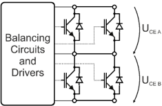
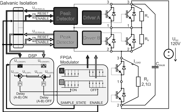
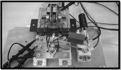
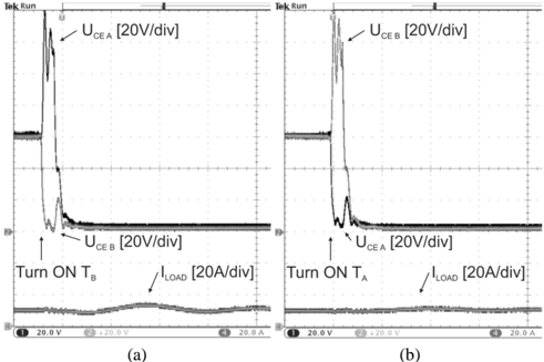
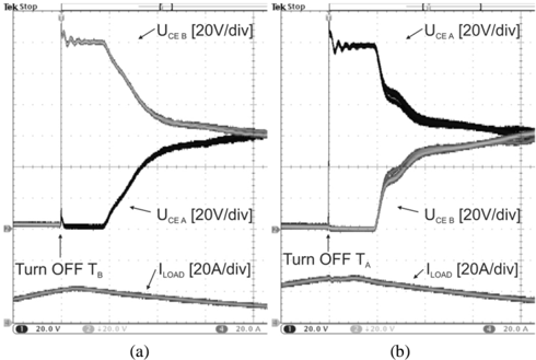
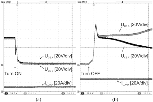
This paper deals with a novel method which allows the serial connection of Insulated Gate Bipolar Transistors (IGBTs). The different dynamic characteristics of serially connected IGBTs during turn ON and OFF cause a short-term overvoltage stress in the transistors. In contrary to the commonly used techniques, the presented method reduces additional commutation losses by actively correcting turn ON and OFF delays. The presented method uses overvoltages as measured by a peak detector. The correction circuit doesn’t require a high speed Analog-Digital converter (ADC) or high speed computation. The target power switch unit consists of two serial connected transistors with two identical parallel branches. The well-known 2-level inverter topology equipped with the power switch unit can be connected directly to the high-voltage grid. This converter topology was demanded by our industry partner for 11 MW mining machines. The paper contains a laboratory experiment conducted on a serial-parallel IGBT power switch unit with a tested output power of 1 kW.DOI: http://dx.doi.org/10.5755/j01.eee.22.1.14110
Overview
The claims and statistics of this paper haven’t been checked yet.
Run the check — free, no account needed. It reads the open-access text and checks the sources it cites.
Integrity signals
Registry
Cites
Statistics
Figures
Verification
Claims the paper makes
The claims and statistics of this paper haven’t been checked yet.
Run the check — free, no account needed. It reads the open-access text and checks the sources it cites.
Claims other papers make about this one
Each is checked against this paper’s own text: does it say what the citing paper says it does?
In the citing paper
“although the paralleling of transistors is an object of significant research [40][41][42][43][44], the application of this topology in the self-resonance architectures requires additional investigation.”
Self-check
Percentages, sums and reported differences re-computed from the paper’s own numbers.
The self-check needs the paper’s full text.
Citations
Cites
No references could be resolved yet.
Research works printed but not linked: 10
- G. Yao, et al. "State-feedback control of a current source inverter- based STATCOM", Elektronika ir Elektrotechnika, no. 3, pp. 17-22, 2010.
- D. Bortis, J. Biela, J. W. Kolar, "Active gate control for current balancing of parallel-connected IGBT modules in solid-state modulators", IEEE Trans. on Plasma Science, vol. 36, no. 5, pp. 2632-2637, 2008. [Online]. Available: http://dx.doi.org/10.1109/ TPS.2008.2003971 · DOI · Paper page
- D. Vinnikov, et al, "Analysis of switching conditions of IGBTs in modified sine wave qZSIs operated with different shoot-through control methods", Elektronika ir Elektrotechnika, no. 5, pp. 45-50, 2011. [Online]. Available: http://dx.doi.org/10.5755/j01.eee.111.5.354 · DOI
- J. W. Baek, D. W. Yoo, H. G. Kim, "High voltage switch using series-connected IGBTs with simple auxiliary circuit", IEEE Industry Applications Conf., 2000, pp. 2237-2242. [Online]. Available: http://dx.doi.org/10.1109/ias.2000.883136 · DOI
- C. Abbate, G. Busatto, L. Fratelli, F. Iannuzzo, B. Cascone, G. Giannini, "Series connection of high power IGBT modules for traction applications", European Conf. on Power Electronics and Applications, 2005. [Online]. Available: http://dx.doi.org/10.1109/ epe.2005.219697 · DOI
- C. Abbate, G. Busatto, F. Iannuzzo, "High-voltage, high-performance switch using series-connected IGBTs", IEEE Trans. Power Electronics, vol. 25, no. 9, pp. 2450-2459, 2010. [Online]. Available: http://dx.doi.org/10.1109/TPEL.2010.2049272 · DOI
- R. Withanage, N. Shammas, "Series connection of insulated gate bipolar transistors (IGBTs)", IEEE Trans. Power Electronics, vol. 27, no. 4, pp. 2204-2212, 2012. [Online]. Available: http://dx.doi.org/ 10.1109/TPEL.2011.2167000 · DOI
- Ting Lu, Zhengming Zhao, Shiqi Ji, Hualong Yu, Liqiang Yuan, "Parameter design of voltage balancing circuit for series connected HV-IGBTs", 7th Int. Power Electronics and Motion Control Conf. (IPEMC), 2012, pp. 1502-1507.
- Z. Dongsheng, D. H. Braun, "A practical series connection technique for multiple IGBT devices", IEEE 32nd Annu. Power Electronics Specialists Conf., (PESC 2001), 2001, pp. 2151-2155. [Online]. Available: http://dx.doi.org/10.1109/pesc.2001.954438 · DOI
- P. Spanik, et al., "Efficiency increase of switched mode power supply through optimization of transistor's commutation mode", Elektronika ir Elektrotechnika, no. 9, pp. 49-52, 2010.
Cited by
Dimitrov, B., Hayatleh, K., Barker, S., & Collier, G. (2021) · Electricity · doi:10.3390/electricity2040026 · Cited by 3
Metadata
- Authors
- Streit, L., Janik, D., & Talla, J.
- Venue
- Elektronika ir Elektrotechnika
- Published
- 2016-02-05
- Volume
- 22
- Issue
- 1
- Pages
- 53-56
- ISSN
- 2029-5731
- 1392-1215
- Cited by
- 3
- References
- 0
About these checks
Registry, retraction, Cites and statistics results are computed, not judged, with one exception: a printed reference that no index lists is read once by a model before it counts as a citation error. Claims are extracted by a model and kept only when their quote appears verbatim in the text; each cited source is then checked, with a model’s help, for whether it says what the claim relies on. Those verdicts can be wrong — read the claim’s quote and the cited source before relying on one.
Statistics and arithmetic are recomputed, not judged.
Confidence bands are shown only for fields calibrated on our annotated test set. None is calibrated yet, so no band is shown.
What counts as a claim ›How we measure confidence ›How we check this ›
Are you an author, or do you see a problem with this page? Request a review
Data sources
Bibliographic data: Semantic Scholar, OpenAlex, Crossref.
Contains information from the Semantic Scholar Academic Graph Datasets, made available under the ODC Attribution License (ODC-BY 1.0).
Semantic Scholar’s data is described in: Kinney, R., et al. (2023). The Semantic Scholar Open Data Platform. arXiv:2301.10140.
