Cited by 35Ion channel regulation and functionIon Transport and Channel RegulationIon Channels and Receptors

The DOI matches its Crossref record; 2 of the 2 references it cites were found in a registry or an index.

Cryo-EM structures of an LRRC8 chimera with native functional properties reveal heptameric assembly

Open access

Published version of a preprint

Abstract

Volume-regulated anion channels (VRACs) mediate volume regulatory Cl - and organic solute efflux from vertebrate cells. VRACs are heteromeric assemblies of LRRC8A-E proteins with unknown stoichiometries. Homomeric LRRC8A and LRRC8D channels have a small pore, hexameric structure. However, these channels are either non-functional or exhibit abnormal regulation and pharmacology, limiting their utility for structure-function analyses. We circumvented these limitations by developing novel homomeric LRRC8 chimeric channels with functional properties consistent with those of native VRAC/LRRC8 channels. We demonstrate here that the LRRC8C-LRRC8A(IL1 25 ) chimera comprising LRRC8C and 25 amino acids unique to the first intracellular loop (IL1) of LRRC8A has a heptameric structure like that of homologous pannexin channels. Unlike homomeric LRRC8A and LRRC8D channels, heptameric LRRC8C-LRRC8A(IL1 25 ) channels have a large-diameter pore similar to that estimated for native VRACs, exhibit normal DCPIB pharmacology, and have higher permeability to large organic anions. Lipid-like densities are located between LRRC8C-LRRC8A(IL1 25 ) subunits and occlude the channel pore. Our findings provide new insights into VRAC/LRRC8 channel structure and suggest that lipids may play important roles in channel gating and regulation.

Overview

The claims and statistics of this paper haven’t been checked yet.

Run the check — free, no account needed. It reads the open-access text and checks the sources it cites.

A few free checks a day · papers already verified open instantly · results are public

Integrity signals

Registry

Crossref · 10.7554/elife.82431

Cites

2 of 2 references verified0 citation errors · 0 not checkable

Statistics

Figures

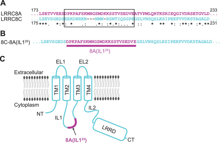
Figure 1. Construct design of 8C-8A(IL125). (A) Sequence alignment of LRRC8A and LRRC8C around the swapped IL125 region. The swapped region in the 8C-8A(IL125) construct is shown inside a black box. The key below amino acid sequences denotes identical (*), conservative (:), and semi-conservative (.) sequences. Space indicates the residues that are not conserved. (B) The amino acid sequence of the 8C-8A(IL125) construct around the swapped IL125 region. (C) Schematic diagram of the 8C-8A(IL125) protein highlighting the relative position of the swapped IL125 region.
Figure 1. Construct design of 8C-8A(IL125). (A) Sequence alignment of LRRC8A and LRRC8C around the swapped IL125 region. The swapped region in the 8C-8A(IL125) construct is shown inside a black box. The key below amino acid sequences denotes identical (*), conservative (:), and semi-conservative (.) sequences. Space indicates the residues that are not conserved. (B) The amino acid sequence of the 8C-8A(IL125) construct around the swapped IL125 region. (C) Schematic diagram of the 8C-8A(IL125) protein highlighting the relative position of the swapped IL125 region.CC BY · PubMed Central
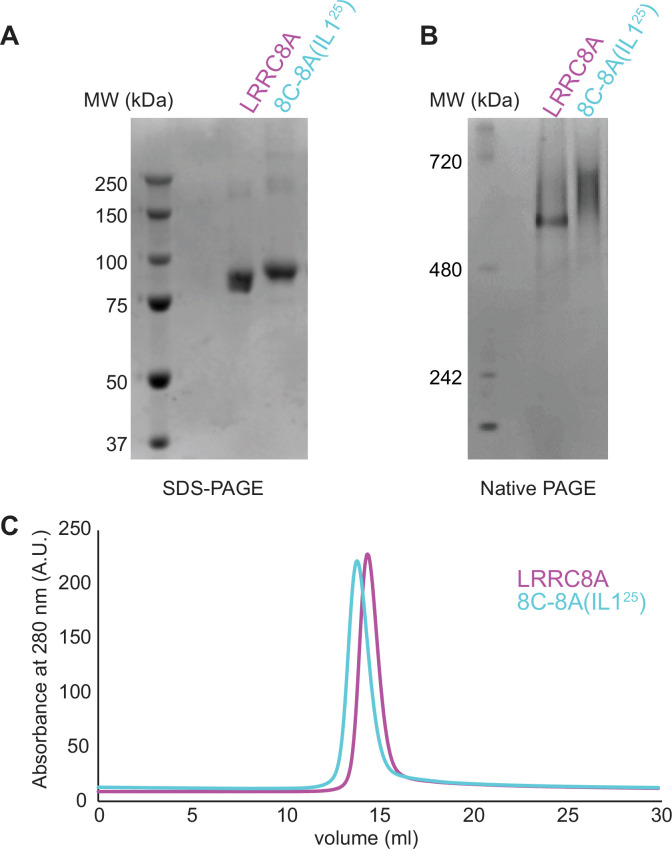
Figure 1—figure supplement 1. Purification of 8C-8A(IL125). SDS-PAGE (A), native-PAGE (B), and size exclusion chromatography (C) analysis of the purified LRRC8A and 8C-8A(IL125) proteins.
Figure 1—figure supplement 1. Purification of 8C-8A(IL125). SDS-PAGE (A), native-PAGE (B), and size exclusion chromatography (C) analysis of the purified LRRC8A and 8C-8A(IL125) proteins.CC BY · PubMed Central
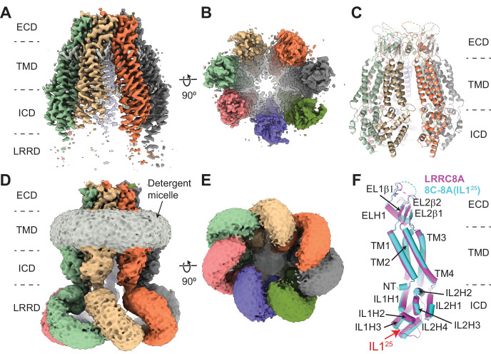
Figure 2. Cryo-electron microscopy (cryo-EM) structure of 8C-8A(IL125). (A–B) Cryo-EM maps of 8C-8A(IL125) class 1 structure viewed through the membrane plane (A) and from the cytoplasm (B). (C) Ribbon representation of the 8C-8A(IL125) class 1 structure viewed through the membrane plane. (D–E) Unsharpened cryo-EM maps of 8C-8A(IL125) class 1 structure viewed through the membrane plane (D) and from the cytoplasm (E), emphasizing low-resolution features. (F) Structural comparison of the 8C-8A(IL125) (cyan) and LRRC8A (magenta, PDB ID: 5ZSU) subunits.
Figure 2. Cryo-electron microscopy (cryo-EM) structure of 8C-8A(IL125). (A–B) Cryo-EM maps of 8C-8A(IL125) class 1 structure viewed through the membrane plane (A) and from the cytoplasm (B). (C) Ribbon representation of the 8C-8A(IL125) class 1 structure viewed through the membrane plane. (D–E) Unsharpened cryo-EM maps of 8C-8A(IL125) class 1 structure viewed through the membrane plane (D) and from the cytoplasm (E), emphasizing low-resolution features. (F) Structural comparison of the 8C-8A(IL125) (cyan) and LRRC8A (magenta, PDB ID: 5ZSU) subunits.CC BY · PubMed Central
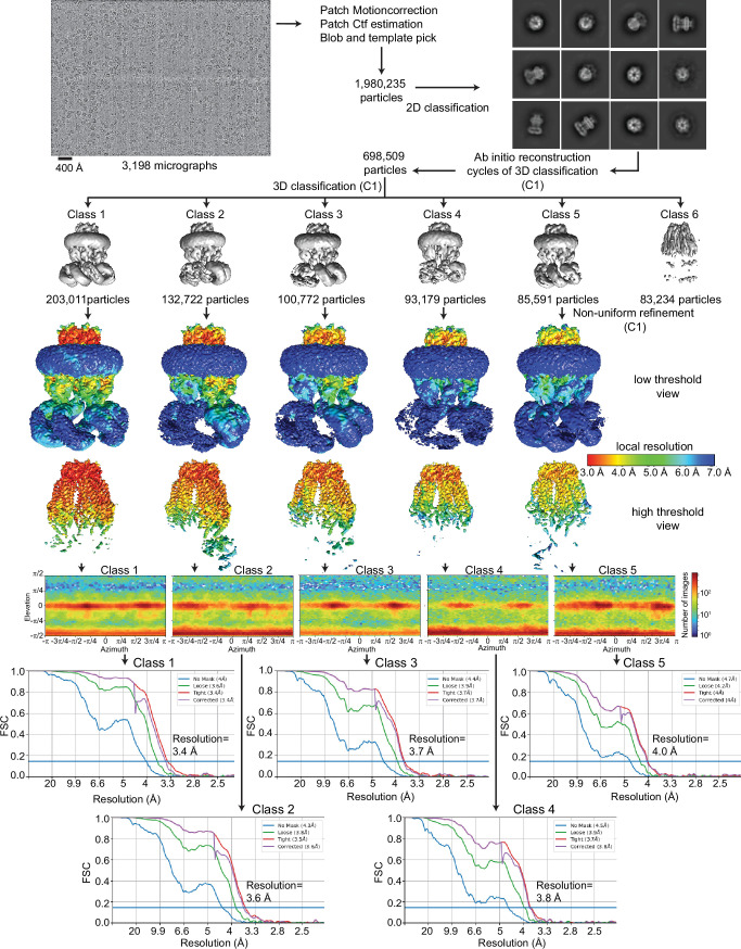
Figure 2—figure supplement 1. Cryo-electron microscopy (cryo-EM) analysis of 8C-8A(IL125). Flowchart detailing the particle selection and refinement procedure to obtain the cryo-EM maps of 8C-8A(IL125). Local resolution maps are shown on maps viewed at two different thresholds in Chimera. FSC curves and angular distributions are shown for the refined classes.
Figure 2—figure supplement 1. Cryo-electron microscopy (cryo-EM) analysis of 8C-8A(IL125). Flowchart detailing the particle selection and refinement procedure to obtain the cryo-EM maps of 8C-8A(IL125). Local resolution maps are shown on maps viewed at two different thresholds in Chimera. FSC curves and angular distributions are shown for the refined classes.CC BY · PubMed Central
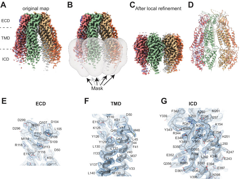
Figure 2—figure supplement 2. Cryo-electron microscopy (cryo-EM) analysis of 8C-8A(IL125). (A) Cryo-EM map of 8C-8A(IL125) class 1 structure colored by individual subunits. (B) Masks used for local refinement of individual subunits are shown as transparent gray surfaces. Each mask was used separately for local refinement. (C) The cryo-EM maps after local refinement for each subunit are aligned onto the original map. (D) Ribbon representation of the 8C-8A(IL125) structure. (E–F) Representative images of the cryo-EM density and the modeled structure covering parts of extracellular domain (ECD) (E), transmembrane domain (TMD) (F), and intracellular domain (ICD) (G). The map in panel (G) is obtained after local refinement, and the maps in panels (E) and (F) are the original maps.
Figure 2—figure supplement 2. Cryo-electron microscopy (cryo-EM) analysis of 8C-8A(IL125). (A) Cryo-EM map of 8C-8A(IL125) class 1 structure colored by individual subunits. (B) Masks used for local refinement of individual subunits are shown as transparent gray surfaces. Each mask was used separately for local refinement. (C) The cryo-EM maps after local refinement for each subunit are aligned onto the original map. (D) Ribbon representation of the 8C-8A(IL125) structure. (E–F) Representative images of the cryo-EM density and the modeled structure covering parts of extracellular domain (ECD) (E), transmembrane domain (TMD) (F), and intracellular domain (ICD) (G). The map in panel (G) is obtained after local refinement, and the maps in panels (E) and (F) are the original maps.CC BY · PubMed Central
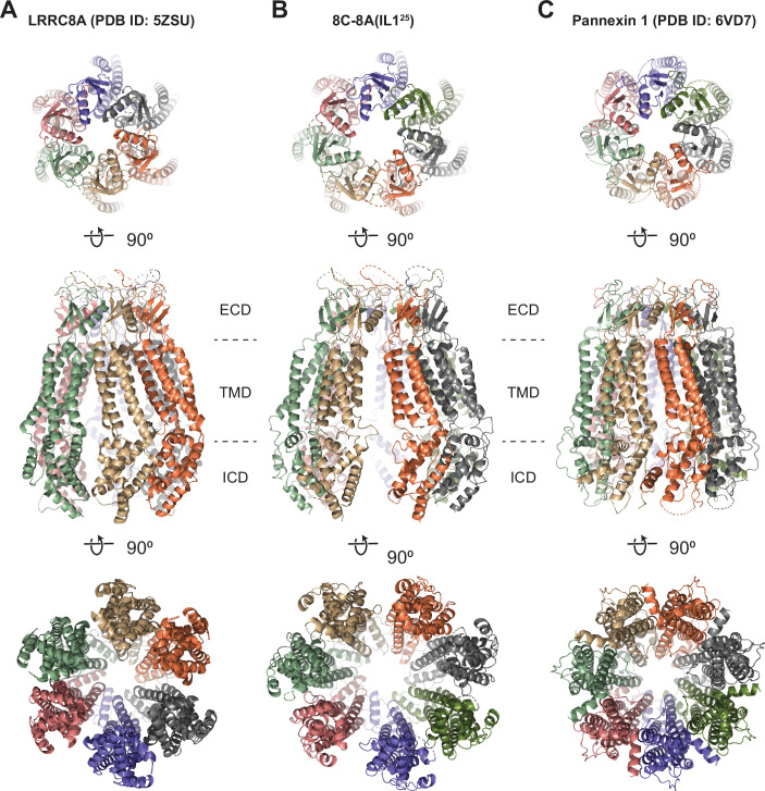
Figure 2—figure supplement 3. Structural comparison of 8C-8A(IL125) to LRRC8A and pannexins. (A–C) Ribbon representations of LRRC8A (PBD ID: 5ZSU) (A), 8C-8A(IL125) class 1 structure (B), and pannexin 1 (PDB ID: 6VD7) (C) viewed from the extracellular space (top), through the membrane plane (middle) and from the cytoplasm (bottom). Leucine-rich repeat motif-containing domains (LRRDs) for 8C-8A(IL125) and LRRC8A were not shown. Each subunit is colored differently.
Figure 2—figure supplement 3. Structural comparison of 8C-8A(IL125) to LRRC8A and pannexins. (A–C) Ribbon representations of LRRC8A (PBD ID: 5ZSU) (A), 8C-8A(IL125) class 1 structure (B), and pannexin 1 (PDB ID: 6VD7) (C) viewed from the extracellular space (top), through the membrane plane (middle) and from the cytoplasm (bottom). Leucine-rich repeat motif-containing domains (LRRDs) for 8C-8A(IL125) and LRRC8A were not shown. Each subunit is colored differently.CC BY · PubMed Central
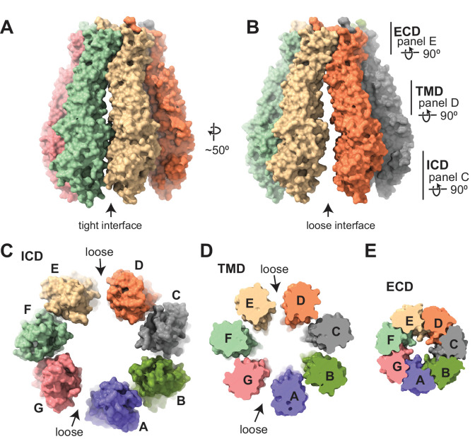
Figure 3. Subunit arrangement of the 8C-8A(IL125) chimera. (A–B) Surface representation of the 8C-8A(IL125) class 1 structure viewed from two sides, highlighting the ‘tight’ (A) and ‘loose’ (B) interfaces. (C–E) Intracellular domain (ICD), transmembrane domain (TMD), and extracellular domains (ECDs) are viewed from the cytoplasm with a depth of view, as shown in panel (B).
Figure 3. Subunit arrangement of the 8C-8A(IL125) chimera. (A–B) Surface representation of the 8C-8A(IL125) class 1 structure viewed from two sides, highlighting the ‘tight’ (A) and ‘loose’ (B) interfaces. (C–E) Intracellular domain (ICD), transmembrane domain (TMD), and extracellular domains (ECDs) are viewed from the cytoplasm with a depth of view, as shown in panel (B).CC BY · PubMed Central
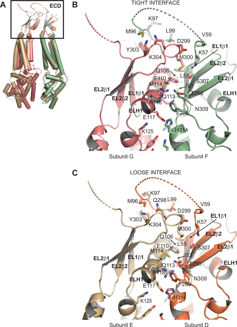
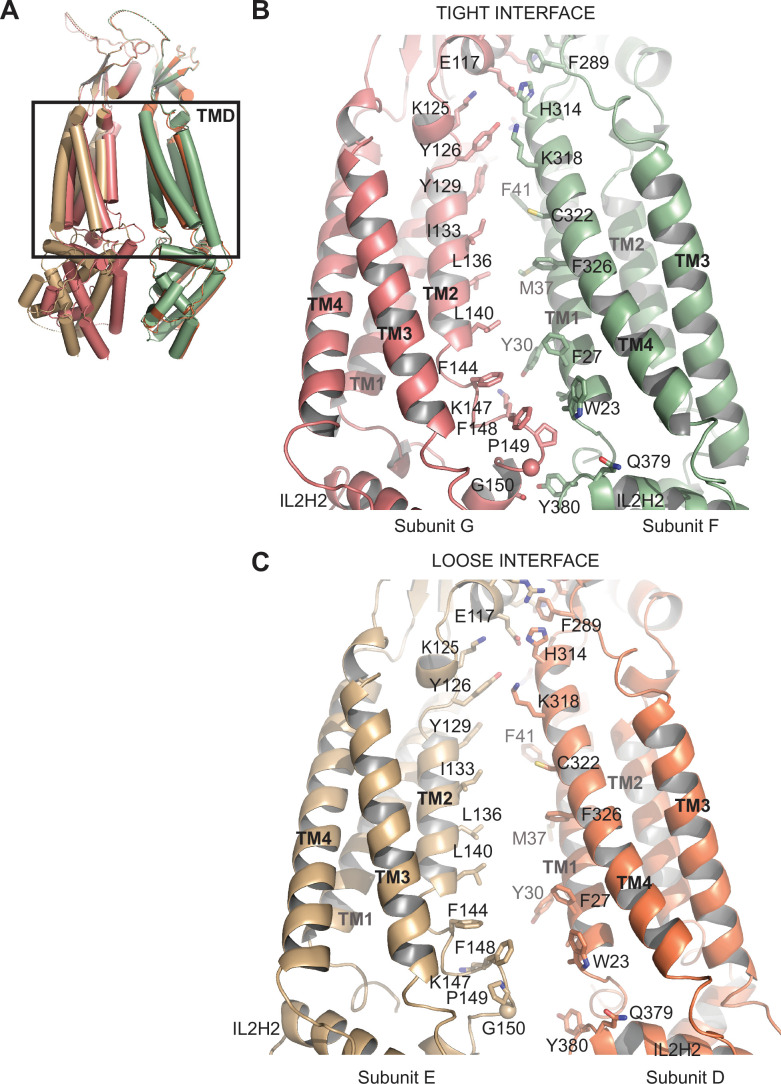
Figure 3—figure supplement 1. Comparison of subunit interfaces. (A) Overlay of two 8C-8A(IL125) subunit pairs of the class 1 structure that form tight and loose interfaces. Structures were aligned on their extracellular domains (ECDs). (B–C) Close-up view of the ECDs forming the tight (B) and loose (C) interfaces. Select residues at the interfaces are shown in stick representation and labeled.
Figure 3—figure supplement 1. Comparison of subunit interfaces. (A) Overlay of two 8C-8A(IL125) subunit pairs of the class 1 structure that form tight and loose interfaces. Structures were aligned on their extracellular domains (ECDs). (B–C) Close-up view of the ECDs forming the tight (B) and loose (C) interfaces. Select residues at the interfaces are shown in stick representation and labeled.CC BY · PubMed Central
Figure 3—figure supplement 2. Comparison of subunit interfaces. (A) Overlay of two 8C-8A(IL125) subunit pairs of the class 1 structure that form tight and loose interfaces. Structures were aligned on their extracellular domains (ECDs). (B–C) Close-up view of the transmembrane domains (TMDs) forming the tight (B) and loose (C) interfaces. Select residues at the interfaces are shown in stick representation and labeled.
Figure 3—figure supplement 2. Comparison of subunit interfaces. (A) Overlay of two 8C-8A(IL125) subunit pairs of the class 1 structure that form tight and loose interfaces. Structures were aligned on their extracellular domains (ECDs). (B–C) Close-up view of the transmembrane domains (TMDs) forming the tight (B) and loose (C) interfaces. Select residues at the interfaces are shown in stick representation and labeled.CC BY · PubMed Central
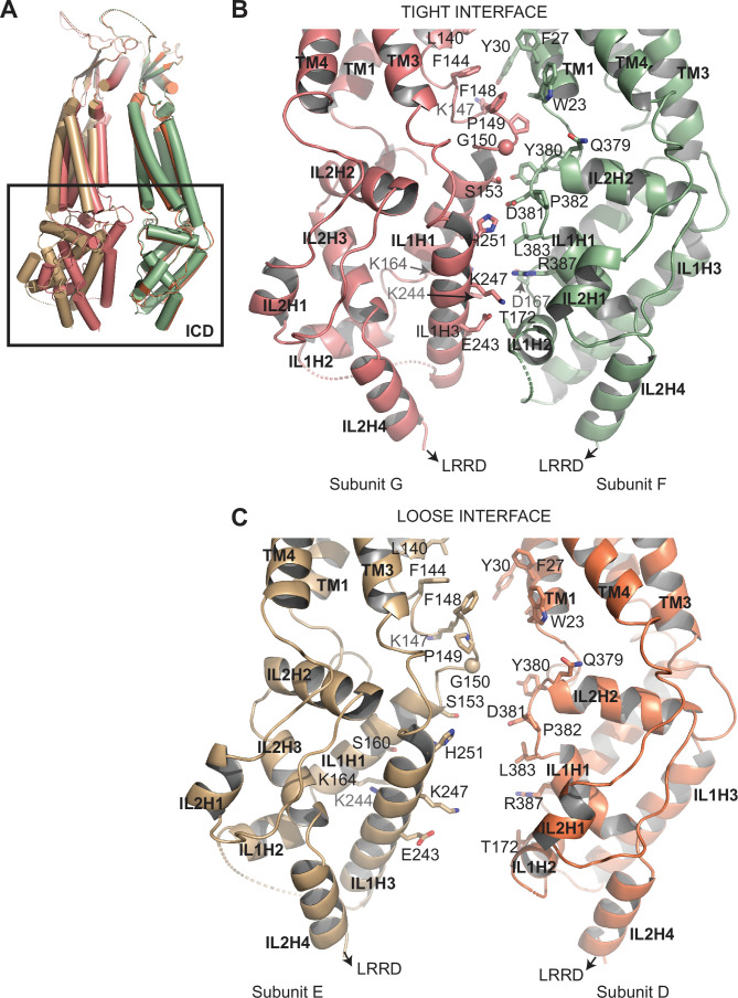
Figure 3—figure supplement 3. Comparison of subunit interfaces. (A) Overlay of two 8C-8A(IL125) subunit pairs of the class 1 structure that form tight and loose interfaces. Structures were aligned on their extracellular domains (ECDs). (B–C) Close-up view of the intracellular domains (ICDs) forming the tight (B) and loose (C) interfaces. Select residues at the interfaces are shown in stick representation and labeled.
Figure 3—figure supplement 3. Comparison of subunit interfaces. (A) Overlay of two 8C-8A(IL125) subunit pairs of the class 1 structure that form tight and loose interfaces. Structures were aligned on their extracellular domains (ECDs). (B–C) Close-up view of the intracellular domains (ICDs) forming the tight (B) and loose (C) interfaces. Select residues at the interfaces are shown in stick representation and labeled.CC BY · PubMed Central
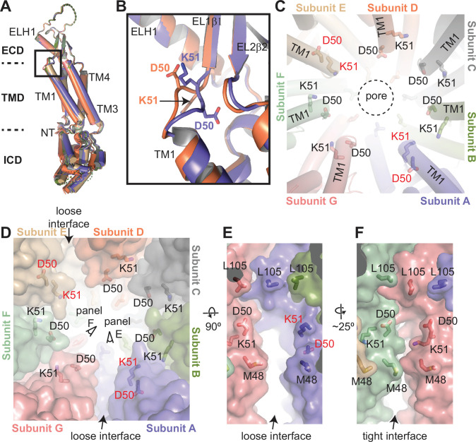
Figure 4. Structural heterogeneity of 8C-8A(IL125) protomers. (A) Structural comparison of the 8C-8A(IL125) subunits in the class 1 structure. The structures are aligned based on their extracellular domains (ECDs). (B) Close-up view of the box region in panel (A), highlighting the structural differences in the loop that connects transmembrane helix 1 (TM1) to EL1β1. Only two subunits are shown. (C) Close-up view of the pore around the residues D50 and K51, which are shown as sticks. The residues that adopt different conformations compared to others are labeled in red. The dashed circle indicates the pore-lining surface. (D) The same view as panel (C) but including the surface representation (transparent) to highlight the distinct interfaces between the subunits. (E–F) Close-up view of the interfaces from the points of view shown in panel (D).
Figure 4. Structural heterogeneity of 8C-8A(IL125) protomers. (A) Structural comparison of the 8C-8A(IL125) subunits in the class 1 structure. The structures are aligned based on their extracellular domains (ECDs). (B) Close-up view of the box region in panel (A), highlighting the structural differences in the loop that connects transmembrane helix 1 (TM1) to EL1β1. Only two subunits are shown. (C) Close-up view of the pore around the residues D50 and K51, which are shown as sticks. The residues that adopt different conformations compared to others are labeled in red. The dashed circle indicates the pore-lining surface. (D) The same view as panel (C) but including the surface representation (transparent) to highlight the distinct interfaces between the subunits. (E–F) Close-up view of the interfaces from the points of view shown in panel (D).CC BY · PubMed Central
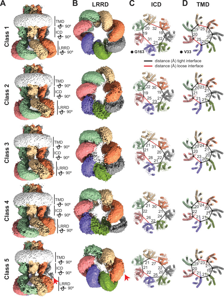
Figure 5. Conformational heterogeneity of 8C-8A(IL125) chimeras. (A–B) Cryo-electron microscopy (cryo-EM) maps (before sharpening) of 8C-8A(IL125) 3D classes viewed through the membrane plane (A) and from the cytoplasm (B). Individual subunits are colored as in Figure 1. The detergent micelle is shown in white. Red arrows point to the weak density of the leucine-rich repeat motif-containing domain (LRRD), which is not located within the LRRD quaternary assembly. Lines represent the depth of the view for LRRD, intracellular domain (ICD), and transmembrane domain (TMD). (C–D) Ribbon representation of the ICD (C) and TMD (D) structures viewed from the cytoplasm with a depth of view indicated in panel (A). The Cα atoms for G163 in ICD and V33 in TMD are shown as spheres. The distances between these atoms in neighboring subunits are shown as lines (in black and red for the tight and loose interfaces, respectively) and labeled in Å.
Figure 5. Conformational heterogeneity of 8C-8A(IL125) chimeras. (A–B) Cryo-electron microscopy (cryo-EM) maps (before sharpening) of 8C-8A(IL125) 3D classes viewed through the membrane plane (A) and from the cytoplasm (B). Individual subunits are colored as in Figure 1. The detergent micelle is shown in white. Red arrows point to the weak density of the leucine-rich repeat motif-containing domain (LRRD), which is not located within the LRRD quaternary assembly. Lines represent the depth of the view for LRRD, intracellular domain (ICD), and transmembrane domain (TMD). (C–D) Ribbon representation of the ICD (C) and TMD (D) structures viewed from the cytoplasm with a depth of view indicated in panel (A). The Cα atoms for G163 in ICD and V33 in TMD are shown as spheres. The distances between these atoms in neighboring subunits are shown as lines (in black and red for the tight and loose interfaces, respectively) and labeled in Å.CC BY · PubMed Central
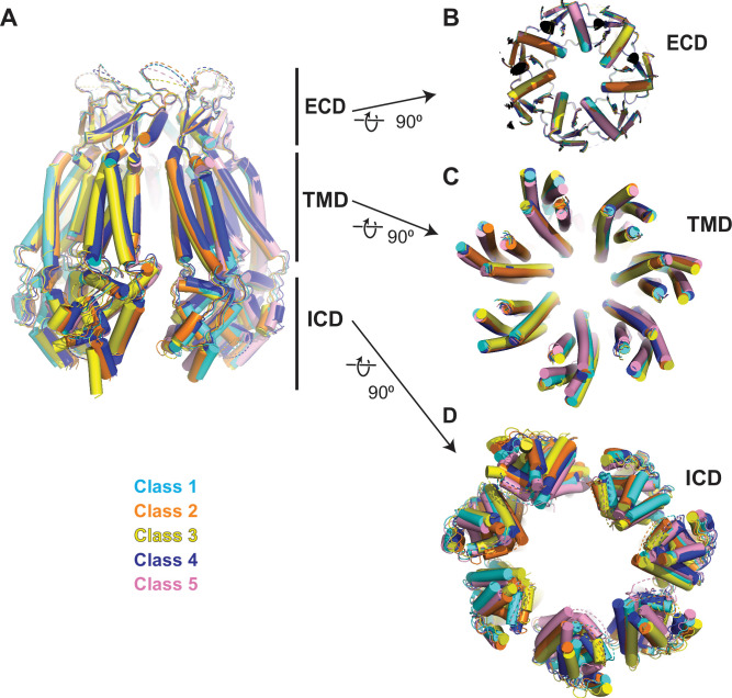
Figure 5—figure supplement 1. Comparison of 8C-8A(IL125) structures. (A) Overlay of 8C-8A(IL125) structures in different classes viewed through the membrane plane. (B–D) Overlay of 8C-8A(IL125) structures in different classes viewed from the intracellular space focusing on the extracellular domain (ECD) (B), transmembrane domain (TMD) (C), and intracellular domain (ICD) (D). Structures are aligned on their ECDs and colored as indicated in the figure. The depths of the views for panels (B)–(D) are indicated in panel (A) with straight lines.
Figure 5—figure supplement 1. Comparison of 8C-8A(IL125) structures. (A) Overlay of 8C-8A(IL125) structures in different classes viewed through the membrane plane. (B–D) Overlay of 8C-8A(IL125) structures in different classes viewed from the intracellular space focusing on the extracellular domain (ECD) (B), transmembrane domain (TMD) (C), and intracellular domain (ICD) (D). Structures are aligned on their ECDs and colored as indicated in the figure. The depths of the views for panels (B)–(D) are indicated in panel (A) with straight lines.CC BY · PubMed Central
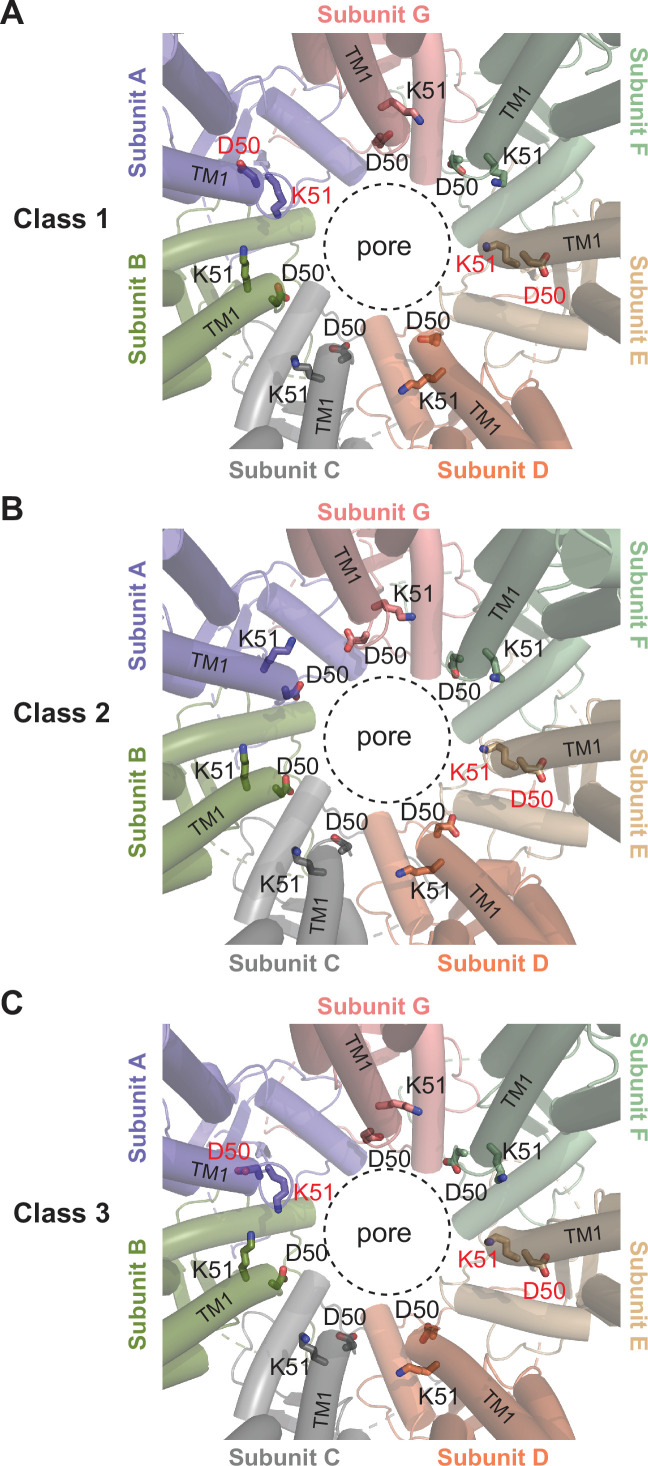
Figure 5—figure supplement 2. Comparison of the D40-K51 loop among different classes. Close-up view of the pore around the residues D50 and K51, which are shown as sticks. The residues that adopt different conformations compared to others are labeled in red. The dashed circle indicates the pore-lining surface.
Figure 5—figure supplement 2. Comparison of the D40-K51 loop among different classes. Close-up view of the pore around the residues D50 and K51, which are shown as sticks. The residues that adopt different conformations compared to others are labeled in red. The dashed circle indicates the pore-lining surface.CC BY · PubMed Central
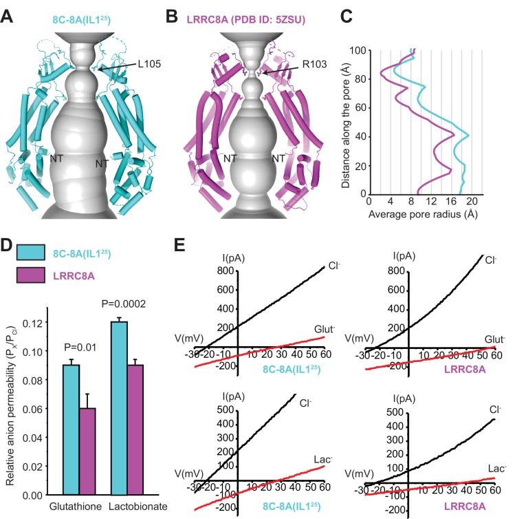
Figure 6. Comparison of channel pores. (A–B) Pore openings of the 8C-8A(IL125) heptameric channel (class 1 structure) (A) and LRRC8A (PDB ID: 5ZSU) homohexameric channel (B) calculated using the software program HOLE (Smart et al., 1996). Only two opposing subunits are shown. Residues forming the constriction sites are shown as sticks. The first modeled residues at the N-termini are labeled as NT. (C) 1D graph of the average radius along the length of the 8C-8A(IL125) (cyan) and LRRC8A (magenta) channel pores. (D) Relative (Px/PCl) glutathione and lactobionate permeabilities calculated from reversal potential changes induced by replacing bath Cl- with the test anion. Values are means ± SEM (N=4–7). Statistical significance was determined using Student’s unpaired t-test. (E) Representative LRRC8A and 8C-8A(IL125) current traces in the presence of bath Cl- or after substitution with glutathione (Glut-) or lactobionate (Lac-). Currents were elicited by ramping membrane voltage from −100 to +100 mV.
Figure 6. Comparison of channel pores. (A–B) Pore openings of the 8C-8A(IL125) heptameric channel (class 1 structure) (A) and LRRC8A (PDB ID: 5ZSU) homohexameric channel (B) calculated using the software program HOLE (Smart et al., 1996). Only two opposing subunits are shown. Residues forming the constriction sites are shown as sticks. The first modeled residues at the N-termini are labeled as NT. (C) 1D graph of the average radius along the length of the 8C-8A(IL125) (cyan) and LRRC8A (magenta) channel pores. (D) Relative (Px/PCl) glutathione and lactobionate permeabilities calculated from reversal potential changes induced by replacing bath Cl- with the test anion. Values are means ± SEM (N=4–7). Statistical significance was determined using Student’s unpaired t-test. (E) Representative LRRC8A and 8C-8A(IL125) current traces in the presence of bath Cl- or after substitution with glutathione (Glut-) or lactobionate (Lac-). Currents were elicited by ramping membrane voltage from −100 to +100 mV.CC BY · PubMed Central
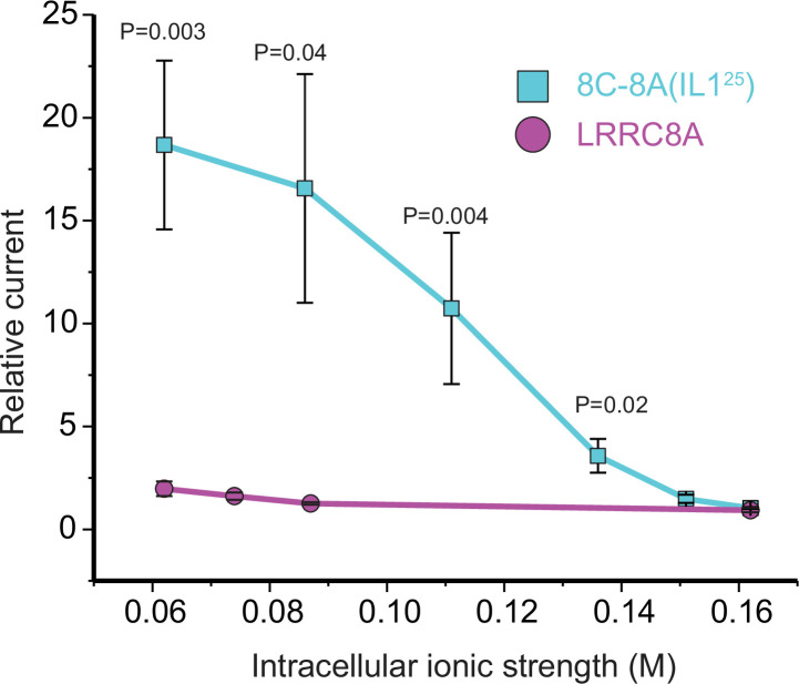
Figure 6—figure supplement 1. Effect of intracellular ionic strength on activation of LRRC8A and the 8C-8A(IL125) chimeric channel. The relative current was quantified as the fold change in current measured immediately after whole-cell access was achieved and currents measured 120 s later. As we have shown previously (Yamada et al., 2021), LRRC8A currents activate only very slowly when intracellular ionic strength is reduced from a normal level of 0.162 to 0.062 M. However, no statistically significant (p>0.9) current activation is detected 120 s after whole-cell access even at the lowest intracellular ionic strength of 0.062 M. In striking contrast, significant (p=0.02) 8C-8A(IL125) current is detected at an intracellular ionic strength of 0.136 M. Reducing ionic strength further leads to more rapid current activation and larger current amplitudes measured at 120 s. The effect of ionic strength on the rate of 8C-8A(IL125) current activation is similar to what we have reported previously for native VRAC/LRRC8 channels (Cannon et al., 1998). The current amplitude was quantified at +60 mV above the measured reversal potential. Values are means ± SEM (N=5–8). Statistical significance was determined using Student’s unpaired t-test.
Figure 6—figure supplement 1. Effect of intracellular ionic strength on activation of LRRC8A and the 8C-8A(IL125) chimeric channel. The relative current was quantified as the fold change in current measured immediately after whole-cell access was achieved and currents measured 120 s later. As we have shown previously (Yamada et al., 2021), LRRC8A currents activate only very slowly when intracellular ionic strength is reduced from a normal level of 0.162 to 0.062 M. However, no statistically significant (p>0.9) current activation is detected 120 s after whole-cell access even at the lowest intracellular ionic strength of 0.062 M. In striking contrast, significant (p=0.02) 8C-8A(IL125) current is detected at an intracellular ionic strength of 0.136 M. Reducing ionic strength further leads to more rapid current activation and larger current amplitudes measured at 120 s. The effect of ionic strength on the rate of 8C-8A(IL125) current activation is similar to what we have reported previously for native VRAC/LRRC8 channels (Cannon et al., 1998). The current amplitude was quantified at +60 mV above the measured reversal potential. Values are means ± SEM (N=5–8). Statistical significance was determined using Student’s unpaired t-test.CC BY · PubMed Central
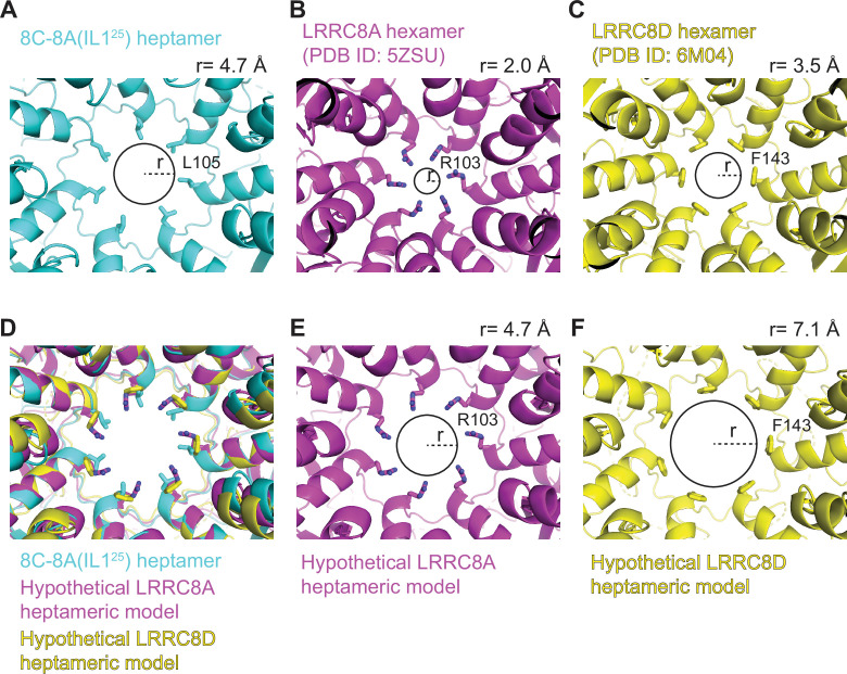
Figure 6—figure supplement 2. Heptameric oligomerization leads to larger pore sizes. (A–C) Close-up cytoplasmic view of the narrowest constriction sites of 8C-8A(IL125) class 1 structure (A), LRRC8A (PDB ID: 5ZSU) (B), and LRRC8D (PDB ID: 6M04) (C). (D) The heptameric LRRC8A and LRRC8D models were obtained by overlaying one of the LRRC8A or LRRC8D subunits on the seven subunits of 8C-8A(IL125) heptamer by aligning the extracellular domains (ECDs). (E–F) Pores of hypothetical LRRC8A (E) and LRRC8D (F) heptamers. Residues forming the constriction are shown as sticks. The circles and the dashed lines represent the solvent-accessible pore size and radius, respectively. The radii of the pores were calculated using the software HOLE (Smart et al., 1996) and shown on top of each panel.
Figure 6—figure supplement 2. Heptameric oligomerization leads to larger pore sizes. (A–C) Close-up cytoplasmic view of the narrowest constriction sites of 8C-8A(IL125) class 1 structure (A), LRRC8A (PDB ID: 5ZSU) (B), and LRRC8D (PDB ID: 6M04) (C). (D) The heptameric LRRC8A and LRRC8D models were obtained by overlaying one of the LRRC8A or LRRC8D subunits on the seven subunits of 8C-8A(IL125) heptamer by aligning the extracellular domains (ECDs). (E–F) Pores of hypothetical LRRC8A (E) and LRRC8D (F) heptamers. Residues forming the constriction are shown as sticks. The circles and the dashed lines represent the solvent-accessible pore size and radius, respectively. The radii of the pores were calculated using the software HOLE (Smart et al., 1996) and shown on top of each panel.CC BY · PubMed Central
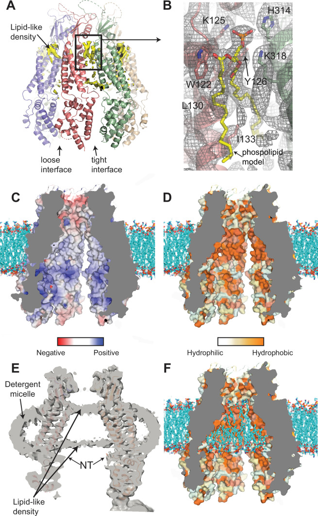
Figure 7. Interaction of lipids with the 8C-8A(IL125) chimera. (A) Ribbon representation of the 8C-8A(IL125) class 1 structure along with the lipid-like cryo-electron microscopy (cryo-EM) densities (yellow) between the subunits viewed through the membrane plane. Loose and tight interfaces are indicated with arrows. (B) Close-up views of the boxed regions in panel (A). The cryo-EM map for the entire region visualized is shown as gray mesh. The phospholipid molecule shown as yellow sticks within the lipid-like density is used for illustration purposes only and not included in the deposited coordinate files. Select residues near the lipid-like densities are shown as sticks and labeled. (C–D) Surface representation of the 8C-8A(IL125) pore colored based on electrostatic charge (C) and hydrophobicity (D). The hypothetical lipid bilayer around the transmembrane domain (TMD) is built using CHARMM-GUI (Wu et al., 2014) and shown as sticks (cyan). Positioning of the protein within the bilayer is calculated using PPM 2.0 (Lomize et al., 2012). (E) A sliced view of the unsharpened cryo-EM map (gray, transparent) with the ribbon representation of the 8C-8A(IL125) class 1 structure. Arrows indicate densities corresponding to pore-blocking lipid-like densities and detergent micelles. (F) Hypothetical interaction of lipids with the inner surface of the pore is shown by placing phospholipids using CHARMM-GUI (Wu et al., 2014). Surface representation of the 8C-8A(IL125) colored based on hydrophobicity as in panel (D).
Figure 7. Interaction of lipids with the 8C-8A(IL125) chimera. (A) Ribbon representation of the 8C-8A(IL125) class 1 structure along with the lipid-like cryo-electron microscopy (cryo-EM) densities (yellow) between the subunits viewed through the membrane plane. Loose and tight interfaces are indicated with arrows. (B) Close-up views of the boxed regions in panel (A). The cryo-EM map for the entire region visualized is shown as gray mesh. The phospholipid molecule shown as yellow sticks within the lipid-like density is used for illustration purposes only and not included in the deposited coordinate files. Select residues near the lipid-like densities are shown as sticks and labeled. (C–D) Surface representation of the 8C-8A(IL125) pore colored based on electrostatic charge (C) and hydrophobicity (D). The hypothetical lipid bilayer around the transmembrane domain (TMD) is built using CHARMM-GUI (Wu et al., 2014) and shown as sticks (cyan). Positioning of the protein within the bilayer is calculated using PPM 2.0 (Lomize et al., 2012). (E) A sliced view of the unsharpened cryo-EM map (gray, transparent) with the ribbon representation of the 8C-8A(IL125) class 1 structure. Arrows indicate densities corresponding to pore-blocking lipid-like densities and detergent micelles. (F) Hypothetical interaction of lipids with the inner surface of the pore is shown by placing phospholipids using CHARMM-GUI (Wu et al., 2014). Surface representation of the 8C-8A(IL125) colored based on hydrophobicity as in panel (D).CC BY · PubMed Central
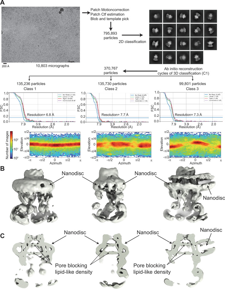
Figure 7—figure supplement 1. Cryo-electron microscopy (cryo-EM) analysis of 8C-8A(IL125) reconstituted in nanodiscs. (A) Flowchart detailing the particle selection and refinement procedure to obtain the cryo-EM maps of the 8C-8A(IL125) nanodiscs. FSC curves and angular distributions are shown. (B–C) Full (B) and sliced (C) views of the cryo-EM maps of the 8C-8A(IL125) nanodiscs.
Figure 7—figure supplement 1. Cryo-electron microscopy (cryo-EM) analysis of 8C-8A(IL125) reconstituted in nanodiscs. (A) Flowchart detailing the particle selection and refinement procedure to obtain the cryo-EM maps of the 8C-8A(IL125) nanodiscs. FSC curves and angular distributions are shown. (B–C) Full (B) and sliced (C) views of the cryo-EM maps of the 8C-8A(IL125) nanodiscs.CC BY · PubMed Central

Verification

Claims the paper makes

The claims and statistics of this paper haven’t been checked yet.

Run the check — free, no account needed. It reads the open-access text and checks the sources it cites.

A few free checks a day · papers already verified open instantly · results are public

Self-check

Percentages, sums and reported differences re-computed from the paper’s own numbers.

The self-check needs the paper’s full text.

Citations

Cites

Research works printed but not linked: 62

  1. Abascal, 2012, LRRC8 proteins share a common ancestor with pannexins, and may form hexameric channels involved in cell-cell communication, Bioessays, 34, 551, 10.1002/bies.201100173 · DOI
  2. Afonine, 2018, Real-space refinement in PHENIX for cryo-EM and crystallography, Acta Crystallographica. Section D, Structural Biology, 74, 531, 10.1107/S2059798318006551 · DOI
  3. Bella, 2008, The leucine-rich repeat structure, Cellular and Molecular Life Sciences, 65, 2307, 10.1007/s00018-008-8019-0 · DOI
  4. Bhat, 2021, Human pannexin 1 channel: insight in structure-function mechanism and its potential physiological roles, Molecular and Cellular Biochemistry, 476, 1529, 10.1007/s11010-020-04002-3 · DOI
  5. Burendei, 2020, Cryo-EM structures of undocked innexin-6 hemichannels in phospholipids, Science Advances, 6, 10.1126/sciadv.aax3157 · DOI
  6. Cannon, 1998, Intracellular ionic strength regulates the volume sensitivity of a swelling-activated anion channel, The American Journal of Physiology, 275, C416, 10.1152/ajpcell.1998.275.2.C416 · DOI
  7. Deneka, 2018, Structure of a volume-regulated anion channel of the LRRC8 family, Nature, 558, 254, 10.1038/s41586-018-0134-y · DOI
  8. Deneka, 2021, Allosteric modulation of LRRC8 channels by targeting their cytoplasmic domains, Nature Communications, 12, 10.1038/s41467-021-25742-w · DOI
  9. Deng, 2020, Cryo-Em structures of the ATP release channel pannexin 1, Nature Structural & Molecular Biology, 27, 373, 10.1038/s41594-020-0401-0 · DOI
  10. Denisov, 2007, Cooperativity in cytochrome P450 3A4: linkages in substrate binding, spin state, uncoupling, and product formation, The Journal of Biological Chemistry, 282, 7066, 10.1074/jbc.M609589200 · DOI
  11. Droogmans, 1999, Sulphonic acid derivatives as probes of pore properties of volume-regulated anion channels in endothelial cells, British Journal of Pharmacology, 128, 35, 10.1038/sj.bjp.0702770 · DOI
  12. Drożdżyk, 2020, Cryo-Em structures and functional properties of CALHM channels of the human placenta, eLife, 9, 10.7554/eLife.55853 · DOI
  13. Emsley, 2004, Coot: model-building tools for molecular graphics, Acta Crystallographica. Section D, Biological Crystallography, 60, 2126, 10.1107/S0907444904019158 · DOI · Paper page
  14. Fitzgerald, 2006, Protein complex expression by using multigene baculoviral vectors, Nature Methods, 3, 1021, 10.1038/nmeth983 · DOI · Paper page
  15. Friard, 2017, Comparative effects of chloride channel inhibitors on LRRC8/VRAC-mediated chloride conductance, Frontiers in Pharmacology, 8, 10.3389/fphar.2017.00328 · DOI
  16. Gaitán-Peñas, 2016, Investigation of LRRC8-mediated volume-regulated anion currents in Xenopus oocytes, Biophysical Journal, 111, 1429, 10.1016/j.bpj.2016.08.030 · DOI
  17. Hubbard, 1993, NACCESS, Computer Program Department of Biochemistry Molecular Biology
  18. Jentsch, 2016, VRACs and other ion channels and transporters in the regulation of cell volume and beyond, Nature Reviews. Molecular Cell Biology, 17, 293, 10.1038/nrm.2016.29 · DOI
  19. Jin, 2020, Cryo-Em structures of human pannexin 1 channel, Cell Research, 30, 449, 10.1038/s41422-020-0310-0 · DOI
  20. Ju, 2015, Force-Induced unfolding of leucine-rich repeats of glycoprotein Ibα strengthens ligand interaction, Biophysical Journal, 109, 1781, 10.1016/j.bpj.2015.08.050 · DOI
  21. Ju, 2016, Cooperative unfolding of distinctive mechanoreceptor domains transduces force into signals, eLife, 5, 10.7554/eLife.15447 · DOI
  22. Kasuya, 2018, Cryo-Em structures of the human volume-regulated anion channel LRRC8, Nature Structural & Molecular Biology, 25, 797, 10.1038/s41594-018-0109-6 · DOI
  23. Kefauver, 2018, Structure of the human volume regulated anion channel, eLife, 7, 10.7554/eLife.38461 · DOI
  24. Kern, 2019, Cryo-Em structures of the DCPIB-inhibited volume-regulated anion channel LRRC8A in lipid nanodiscs, eLife, 8, 10.7554/eLife.42636 · DOI
  25. Kern, 2022, Structural Basis for Assembly and Lipid-Mediated Gating of LRRC8A:C Volume-Regulated Anion Channels, 10.1101/2022.07.31.502239 · DOI
  26. Kobe, 2001, The leucine-rich repeat as a protein recognition motif, Current Opinion in Structural Biology, 11, 725, 10.1016/s0959-440x(01)00266-4 · DOI
  27. König, 2019, A FRET sensor of C-terminal movement reveals VRAC activation by plasma membrane DAG signaling rather than ionic strength, eLife, 8, 10.7554/eLife.45421 · DOI
  28. Kuzuya, 2022, Structures of human pannexin-1 in nanodiscs reveal gating mediated by dynamic movement of the N terminus and phospholipids, Science Signaling, 15, 10.1126/scisignal.abg6941 · DOI
  29. Lomize, 2012, OPM database and PPM web server: resources for positioning of proteins in membranes, Nucleic Acids Research, 40, D370, 10.1093/nar/gkr703 · DOI
  30. Mastronarde, 2005, Automated electron microscope tomography using robust prediction of specimen movements, Journal of Structural Biology, 152, 36, 10.1016/j.jsb.2005.07.007 · DOI
  31. Matsushima, 2019, Leucine rich repeat proteins: sequences, mutations, structures and diseases, Protein and Peptide Letters, 26, 108, 10.2174/0929866526666181208170027 · DOI
  32. Michalski, 2020, The cryo-EM structure of pannexin 1 reveals unique motifs for ion selection and inhibition, eLife, 9, 10.7554/eLife.54670 · DOI
  33. Morin, 2013, Collaboration gets the most out of software, eLife, 2, 10.7554/eLife.01456 · DOI
  34. Mou, 2020, Structural basis for gating mechanism of pannexin 1 channel, Cell Research, 30, 452, 10.1038/s41422-020-0313-x · DOI
  35. Nakamura, 2020, Cryo-em structure of the volume-regulated anion channel LRRC8D isoform identifies features important for substrate permeation, Communications Biology, 3, 10.1038/s42003-020-0951-z · DOI
  36. Pettersen, 2004, UCSF chimera--a visualization system for exploratory research and analysis, Journal of Computational Chemistry, 25, 1605, 10.1002/jcc.20084 · DOI
  37. Pettersen, 2021, UCSF chimerax: structure visualization for researchers, educators, and developers, Protein Science, 30, 70, 10.1002/pro.3943 · DOI
  38. Punjani, 2017, CryoSPARC: algorithms for rapid unsupervised cryo-EM structure determination, Nature Methods, 14, 290, 10.1038/nmeth.4169 · DOI · Paper page
  39. Qiu, 2014, SWELL1, a plasma membrane protein, is an essential component of volume-regulated anion channel, Cell, 157, 447, 10.1016/j.cell.2014.03.024 · DOI · Paper page
  40. Qu, 2020, Cryo-Em structure of human heptameric pannexin 1 channel, Cell Research, 30, 446, 10.1038/s41422-020-0298-5 · DOI
  41. Rasmussen, 2019, Structure of the mechanosensitive channel MscS embedded in the membrane bilayer, Journal of Molecular Biology, 431, 3081, 10.1016/j.jmb.2019.07.006 · DOI
  42. Reddy, 2019, Molecular basis of force-from-lipids gating in the mechanosensitive channel MscS, eLife, 8, 10.7554/eLife.50486 · DOI
  43. Ritchie, 2009, Chapter 11-reconstitution of membrane proteins in phospholipid bilayer nanodiscs, Methods in Enzymology, 464, 211, 10.1016/S0076-6879(09)64011-8 · DOI
  44. Ruan, 2020, Structures of human pannexin 1 reveal ion pathways and mechanism of gating, Nature, 584, 646, 10.1038/s41586-020-2357-y · DOI
  45. Rutz, 2023, Structure of a volume-regulated heteromeric LRRC8A/C channel, Nature Structural & Molecular Biology, 30, 52, 10.1038/s41594-022-00899-0 · DOI
  46. Sabirov, 2005, Atp release via anion channels, Purinergic Signalling, 1, 311, 10.1007/s11302-005-1557-0 · DOI
  47. Smart, 1996, Hole: a program for the analysis of the pore dimensions of ion channel structural models, Journal of Molecular Graphics, 14, 354, 10.1016/s0263-7855(97)00009-x · DOI
  48. Strange, 2019, A 30-year journey from volume-regulated anion currents to molecular structure of the LRRC8 channel, The Journal of General Physiology, 151, 100, 10.1085/jgp.201812138 · DOI
  49. Syeda, 2016, LRRC8 proteins form volume-regulated anion channels that sense ionic strength, Cell, 164, 499, 10.1016/j.cell.2015.12.031 · DOI
  50. Syrjanen, 2020, Structure and assembly of calcium homeostasis modulator proteins, Nature Structural & Molecular Biology, 27, 150, 10.1038/s41594-019-0369-9 · DOI
  51. Ternovsky, 2004, Sizing the pore of the volume-sensitive anion channel by differential polymer partitioning, FEBS Letters, 576, 433, 10.1016/j.febslet.2004.09.051 · DOI
  52. Ullrich, 2016, Inactivation and anion selectivity of volume-regulated anion channels (vracs) depend on C-terminal residues of the first extracellular loop, The Journal of Biological Chemistry, 291, 17040, 10.1074/jbc.M116.739342 · DOI
  53. Voss, 2014, Identification of LRRC8 heteromers as an essential component of the volume-regulated anion channel VRAC, Science, 344, 634, 10.1126/science.1252826 · DOI
  54. Williams, 2018, MolProbity: more and better reference data for improved all-atom structure validation, Protein Science, 27, 293, 10.1002/pro.3330 · DOI · Paper page
  55. Wu, 2014, CHARMM-GUI membrane builder toward realistic biological membrane simulations, Journal of Computational Chemistry, 35, 1997, 10.1002/jcc.23702 · DOI
  56. Yamada, 2016, Leucine-rich repeat containing protein LRRC8A is essential for swelling-activated cl- currents and embryonic development in zebrafish, Physiological Reports, 4, 10.14814/phy2.12940 · DOI
  57. Yamada, 2018, Intracellular and extracellular loops of LRRC8 are essential for volume-regulated anion channel function, The Journal of General Physiology, 150, 1003, 10.1085/jgp.201812016 · DOI
  58. Yamada, 2021, LRRC8A homohexameric channels poorly recapitulate VRAC regulation and pharmacology, American Journal of Physiology. Cell Physiology, 320, C293, 10.1152/ajpcell.00454.2020 · DOI
  59. Zhang, 2021, Visualization of the mechanosensitive ion channel mscs under membrane tension, Nature, 590, 509, 10.1038/s41586-021-03196-w · DOI
  60. Zheng, 2017, MotionCor2: anisotropic correction of beam-induced motion for improved cryo-electron microscopy, Nature Methods, 14, 331, 10.1038/nmeth.4193 · DOI
  61. Zhou, 2018, LRRC8 N termini influence pore properties and gating of volume-regulated anion channels (vracs), The Journal of Biological Chemistry, 293, 13440, 10.1074/jbc.RA118.002853 · DOI
  62. Zivanov, 2018, New tools for automated high-resolution cryo-EM structure determination in RELION-3, eLife, 7, 10.7554/eLife.42166 · DOI

Metadata

Authors
Takahashi, H., Yamada, T., Denton, J. S., Strange, K., & Karakas, E.
Affiliations
  • Vanderbilt University (US)
  • Vanderbilt University Medical Center (US)
  • Department of Molecular Physiology and Biophysics, School of Medicine, Vanderbilt University
Venue
eLife
Published
2023-03-10
Volume
12
ISSN
2050-084X (ISSN-L)
OpenAlex
W4323812162
Cited by
35
References
2
Citations by year
2026: 11 · 2025: 8 · 2024: 8 · 2023: 7
FWCI
3.02
Type
journal article
Language
en
Open access
Locations
  • eLife (publishedVersion, cc-by)
  • bioRxiv (Cold Spring Harbor Laboratory) (acceptedVersion, cc-by-nc-nd)
  • PubMed Central (publishedVersion, cc-by)
  • PubMed (publishedVersion)
  • DOAJ (DOAJ: Directory of Open Access Journals) (submittedVersion, cc-by-sa)
Funders
National Institute of Diabetes and Digestive and Kidney Diseases (DK51610)
Topics
  • Life Sciences › Biochemistry, Genetics and Molecular Biology › Molecular Biology › Ion channel regulation and function
  • Life Sciences › Biochemistry, Genetics and Molecular Biology › Molecular Biology › Ion Transport and Channel Regulation
  • Life Sciences › Neuroscience › Sensory Systems › Ion Channels and Receptors
Keywords
volume-regulated anion channel, LRRC8A, chimeric channels, channel structure, DCPIB, channel gating, pannexin channels, homomeric channels
MeSH terms
Anions, Biological Transport, Membrane Proteins, Cryoelectron Microscopy

About these checks

Registry, retraction, Cites and statistics results are computed, not judged, with one exception: a printed reference that no index lists is read once by a model before it counts as a citation error. Claims are extracted by a model and kept only when their quote appears verbatim in the text; each cited source is then checked, with a model’s help, for whether it says what the claim relies on. Those verdicts can be wrong — read the claim’s quote and the cited source before relying on one.

Statistics and arithmetic are recomputed, not judged.

Confidence bands are shown only for fields calibrated on our annotated test set. None is calibrated yet, so no band is shown.

What counts as a claim ›How we measure confidence ›How we check this ›

Are you an author, or do you see a problem with this page? Request a review