

The DOI matches its Crossref record; 43 of the 43 references it cites were found in a registry or an index.
Real-time pressure mapping smart insole system based on a controllable vertical pore dielectric layer
Open accessAbstract
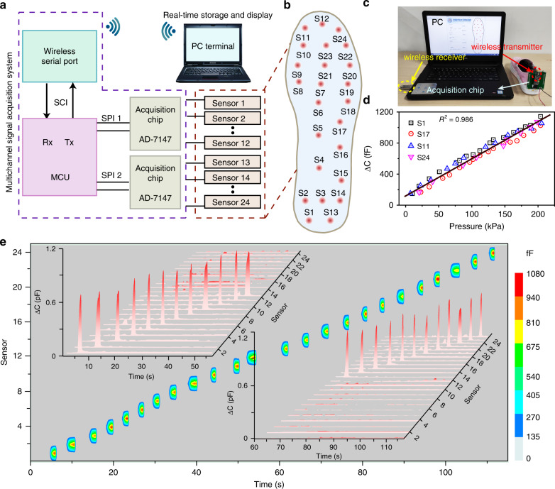
Real-time monitoring of plantar pressure has significant applications in wearable biosensors, sports injury detection, and early diagnostics. Herein, an all-in-one insole composed of 24 capacitive pressure sensors (CPSs) with vertical pores in an elastic dielectric layer is fabricated by laser cutting. Optimized CPSs with a hexagonal configuration and a pore size of 600 μm possess good linearity over a wide detection range of 0–200 kPa with a sensitivity of 12 × 10 –3 kPa −1 . Then, a smart system including the all-in-one insole with the 24 CPS array, a data acquisition system with a wireless transmitter and a PC terminal with a wireless receiver is established for real-time monitoring to realize static and dynamic plantar pressure mapping. Based on this smart insole system, various standing and yoga postures can be distinguished, and variations in the center of gravity during walking can be recognized. This intelligent insole system provides great feasible supervision for health surveillance, injury prevention, and athlete training.
Overview
The claims and statistics of this paper haven’t been checked yet.
Free: it reads the open-access text and checks the first 5 claims that cite a source we can check. Create a free account to check every claim.
Integrity signals
Registry
Cites
Statistics
Figures




Verification
Claims the paper makes
The claims and statistics of this paper haven’t been checked yet.
Free: it reads the open-access text and checks the first 5 claims that cite a source we can check. Create a free account to check every claim.
Claims other papers make about this one
Each is checked against this paper’s own text: does it say what the citing paper says it does?
In the citing paper
“| Slips and falls | Plantar pressures | Pressure sensor | 196 |”
From Recent advances in intelligent wearable systems: from multiscale biomechanical features towards human motion intent prediction (2026) · cites this paper as [196]
Self-check
Percentages, sums and reported differences re-computed from the paper’s own numbers.
The self-check needs the paper’s full text.
Citations
Cites
A wearable and highly sensitive pressure sensor with ultrathin gold nanowires
Gong, S., Schwalb, W., Wang, Y., Chen, Y., Tang, Y., Si, J., Shirinzadeh, B., & Cheng, W. (2014) · Nature Communications · doi:10.1038/ncomms4132 · Cited by 2,064
Skin-inspired highly stretchable and conformable matrix networks for multifunctional sensing
Hua, Q., Sun, J., Liu, H., Bao, R., Yu, R., Zhai, J., Pan, C., & Wang, Z. L. (2018) · Nature Communications · doi:10.1038/s41467-017-02685-9 · Cited by 1,413
Self-citationChoong, C., Shim, M., Lee, B., Jeon, S., Ko, D., Kang, T., Bae, J., Lee, S. H., Byun, K., Im, J., et al. (2014) · Advanced Materials · doi:10.1002/adma.201305182 · Cited by 1,252
Gait Analysis Using Wearable Sensors
Tao, W., Liu, T., Zheng, R., & Feng, H. (2012) · Sensors · doi:10.3390/s120202255 · Cited by 1,165
Recent Progress in Electronic Skin
Wang, X., Dong, L., Zhang, H., Yu, R., Pan, C., & Wang, Z. L. (2015) · Advanced Science · doi:10.1002/advs.201500169 · Cited by 976
Self-citationPan, C., Dong, L., Zhu, G., Niu, S., Yu, R., Yang, Q., Liu, Y., & Wang, Z. L. (2013) · Nature Photonics · doi:10.1038/nphoton.2013.191 · Cited by 741
Self-citationAbnormality of Gait as a Predictor of Non-Alzheimer's Dementia
Verghese, J., Lipton, R. B., Hall, C. B., Kuslansky, G., Katz, M. J., & Buschke, H. (2002) · New England Journal of Medicine · doi:10.1056/nejmoa020441 · Cited by 690
Multifunctional materials for implantable and wearable photonic healthcare devices
Lee, G.-H., Moon, H., Kim, H., Lee, G. H., Kwon, W., Yoo, S., Myung, D., Yun, S. H., Bao, Z., & Hahn, S. K. (2020) · Nature Reviews Materials · doi:10.1038/s41578-019-0167-3 · Cited by 667
Park, S., Kim, H., Vosgueritchian, M., Cheon, S., Kim, H., Koo, J. H., Kim, T. R., Lee, S., Schwartz, G., Chang, H., et al. (2014) · Advanced Materials · doi:10.1002/adma.201402574 · Cited by 565
Tee, B. C. ‐., Chortos, A., Dunn, R. R., Schwartz, G., Eason, E., & Bao, Z. (2014) · Advanced Functional Materials · doi:10.1002/adfm.201400712 · Cited by 538
Cited by
Flexible and Stretchable Capacitive Sensors with Different Microstructures
Qin, J., Yin, L., Hao, Y., Zhong, S., Zhang, D., Bi, K., Zhang, Y., Zhao, Y., & Dang, Z. (2021) · Advanced Materials · doi:10.1002/adma.202008267 · Cited by 616
Ha, K., Zhang, W., Jang, H., Kang, S., Wang, L., Tan, P., Hwang, H., & Lu, N. (2021) · Advanced Materials · doi:10.1002/adma.202103320 · Cited by 354
Technology evolution from self-powered sensors to AIoT enabled smart homes
Dong, B., Shi, Q., Yang, Y., Wen, F., Zhang, Z., & Lee, C. (2021) · Nano Energy · doi:10.1016/j.nanoen.2020.105414 · Cited by 313
Ionic Flexible Sensors: Mechanisms, Materials, Structures, and Applications
Zhao, C., Wang, Y., Tang, G., Ru, J., Zhu, Z., Li, B., Guo, C. F., Li, L., & Zhu, D. (2022) · Advanced Functional Materials · doi:10.1002/adfm.202110417 · Cited by 290
Self-citationChen, S., Peng, C., Yang, B., Lin, J., Zhou, L., Jiang, Z., Liu, Z., Liu, Y., & Tang, L. (2026) · npj Artificial Intelligence · doi:10.1038/s44387-026-00083-5 · Cited by 9
Self-citation
Metadata
- Authors
- Tao, J., Dong, M., Li, L., Wang, C., Li, J., Liu, Y., Bao, R., & Pan, C.
- Affiliations
- Shenzhen University (CN)
- Chinese Academy of Sciences (CN)
- Guangxi University (CN)
- Corresponding author
- Bao, Rongrong
- Pan, Caofeng
- Venue
- Microsystems & Nanoengineering
- Published
- 2020-08-10
- Volume
- 6
- Issue
- 1
- Pages
- 62-62
- ISSN
- 2055-7434 (ISSN-L)
- PMC
- PMC8433384
- OpenAlex
- W3047730168
- Cited by
- 159
- References
- 43
- Citations by year
- 2026: 17 · 2025: 40 · 2024: 30 · 2023: 32 · 2022: 19 · 2021: 20 · 2020: 1
- FWCI
- 5.66
- Type
- journal article
- Language
- en
- Open access
- gold
- doi.org
- Licence
- cc-by
- creativecommons.org/licenses/by/4.0 (tdm)
- creativecommons.org/licenses/by/4.0 (vor)
- Locations
- Microsystems & Nanoengineering (publishedVersion, cc-by)
- Europe PMC (PubMed Central) (publishedVersion, other-oa)
- PubMed Central (publishedVersion, cc-by)
- PubMed (publishedVersion)
- Funders
- National Natural Science Foundation of China (51432005, 61805015,, 51622205, Z180011, 61675027, 2016YFA0202703, 61804011)
- Chinese Academy of Sciences (51432005)
- University of Chinese Academy of Sciences
- Topics
- Physical Sciences › Engineering › Biomedical Engineering › Advanced Sensor and Energy Harvesting Materials
- Physical Sciences › Engineering › Biomedical Engineering › Non-Invasive Vital Sign Monitoring
- Physical Sciences › Engineering › Electrical and Electronic Engineering › Nanomaterials and Printing Technologies
- Keywords
- smart insoles, capacitive pressure sensor, wearable biosensors, real-time pressure monitoring, sports injury prevention, wireless data acquisition
About these checks
Registry, retraction, Cites and statistics results are computed, not judged, with one exception: a printed reference that no index lists is read once by a model before it counts as a citation error. Claims are extracted by a model and kept only when their quote appears verbatim in the text; each cited source is then checked, with a model’s help, for whether it says what the claim relies on. Those verdicts can be wrong — read the claim’s quote and the cited source before relying on one.
Statistics and arithmetic are recomputed, not judged.
Confidence bands are shown only for fields calibrated on our annotated test set. None is calibrated yet, so no band is shown.
What counts as a claim ›How we measure confidence ›How we check this ›
Are you an author, or do you see a problem with this page? Request a review
How to cite
Cite CoChat for the checks on this page, and the paper for its own findings.
- This page
- CoChat. (2026). Citation check: Real-time pressure mapping smart insole system based on a controllable vertical pore dielectric layer. https://app.cochat.ai/papers/10.1038/s41378-020-0171-1
- The paper
- Tao, J., Dong, M., Li, L., Wang, C., Li, J., Liu, Y., Bao, R., & Pan, C. (2020). Real-time pressure mapping smart insole system based on a controllable vertical pore dielectric layer. Microsystems & Nanoengineering. https://doi.org/10.1038/s41378-020-0171-1
Data sources
Bibliographic data: Semantic Scholar, OpenAlex, Crossref.
Contains information from the Semantic Scholar Academic Graph Datasets, made available under the ODC Attribution License (ODC-BY 1.0).
Semantic Scholar’s data is described in: Kinney, R., et al. (2023). The Semantic Scholar Open Data Platform. arXiv:2301.10140.
