

The DOI matches its Crossref record; 19 of the 22 references it cites were found in a registry or an index.
Process Advantages of Direct CO2 to Methanol Synthesis
Open accessAbstract
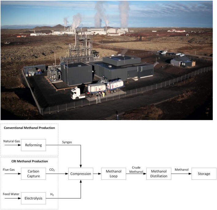
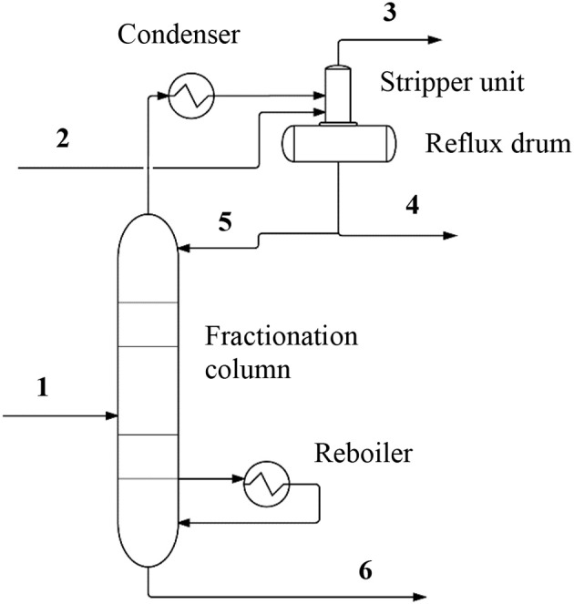
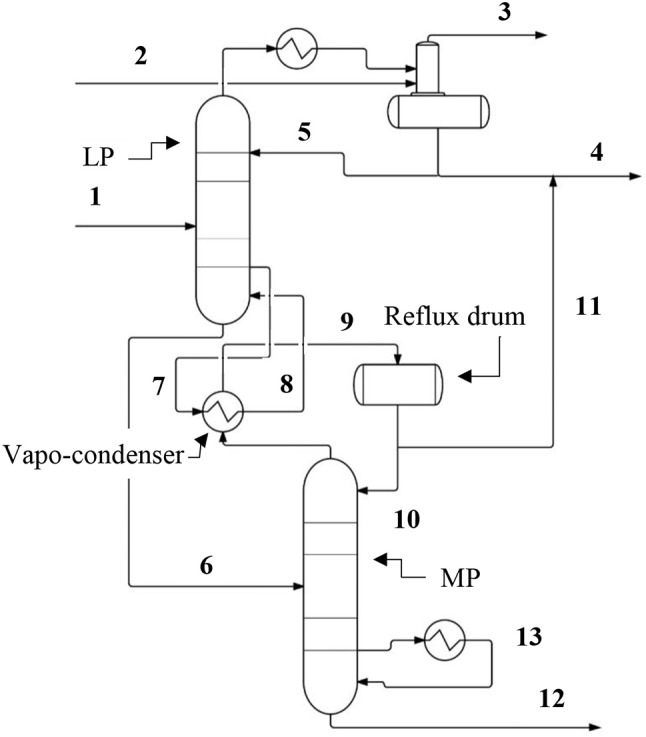
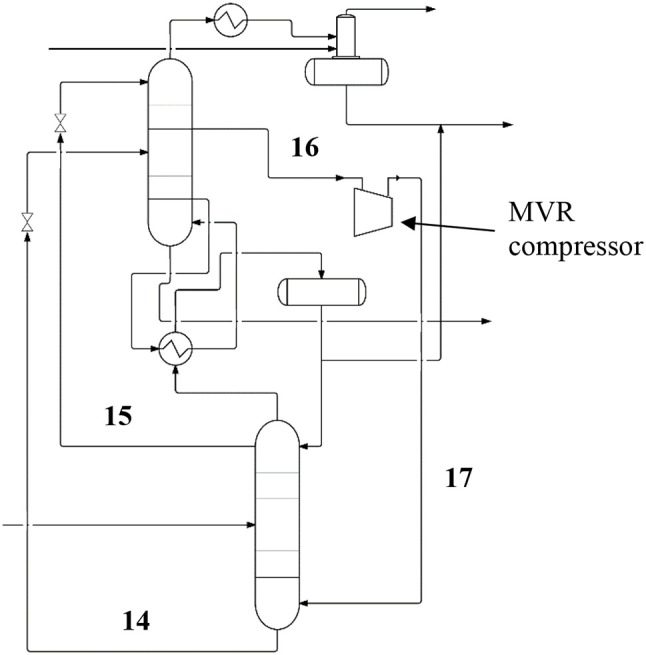
Developing a laboratory scale or pilot scale chemical process into industrial scale is not trivial. The direct conversion of CO2 to methanol, and concomitant production of hydrogen from water electrolysis on large scale, are no exception. However, when successful, there are certain benefits to this process over the conventional process for producing methanol, both economic and environmental. In this article, we highlight some aspects that are unique to the process of converting pure CO2 to methanol. Starting from pure CO2 and a separate pure source of H2, rather than a mixture of CO, CO2 and H2 as is the case with syngas, simplifies the chemistry, and therefore also changes the reaction and purification processes from conventional methanol producing industrial plants. At the core of the advantages is that the reaction impurities are essentially limited to only water and dissolved CO2 in the crude methanol. In this paper we focus on several aspects of the process that direct conversion of CO2 to methanol enjoys over existing methods from conventional syngas. In particular, we discuss processes for removing CO2 from a methanol synthesis intermediate product stream by way of a stripper unit in an overhead stream of a distillation column, as well as aspects of a split tower design for the distillation column with an integrated vapo-condenser and optionally also featuring mechanical vapor re-compression. Lastly, we highlight some differences in reactor design for the present system over those used in conventional plants.
Overview
The claims and statistics of this paper haven’t been checked yet.
Run the check — free, no account needed. It reads the open-access text and checks the sources it cites.
Integrity signals
Registry
Cites
Statistics
Figures
Verification
Claims the paper makes
The claims and statistics of this paper haven’t been checked yet.
Run the check — free, no account needed. It reads the open-access text and checks the sources it cites.
Claims other papers make about this one
Each is checked against this paper’s own text: does it say what the citing paper says it does?
The source backs part of the claim, not all of it — or backs it for a different population, condition or comparison.
In the citing paper
“With a high recycling ratio in the synthesis process, CO2-to-methanol conversion rates approach 100 % [29]”
From Locked in on RFNBOs – Will EU mandates for drop-in synthetic aviation fuels lead to decreased energy- and cost-efficiency? (2026) · cites this paper as [29]
Experimental — accuracy not yet measured
Self-check
Percentages, sums and reported differences re-computed from the paper’s own numbers.
The self-check needs the paper’s full text.
Citations
Cites
Wirtschafter, D. D. (2009) · Canadian Medical Association Journal · doi:10.1503/cmaj.109-2013 · Cited by 12,235
Artz, J., Müller, T. E., Thenert, K., Kleinekorte, J., Meys, R., Sternberg, A., Bardow, A., & Leitner, W. (2017) · Chemical Reviews · doi:10.1021/acs.chemrev.7b00435 · Cited by 2,489 · cited 1×
“One approach to a more sustainable future is to use CO2 as the carbon source for fuels and carbon-based materials that are currently only derived from coal, oil and natural gas (Peters et al., 2011; Aresta et al., 2016; Landälv, 2017; Artz et al., 2018).”
BackgroundBeyond Oil and Gas: The Methanol Economy
Prakash, G. S., Olah, G. A., & Goeppert, A. (2011) · ECS Transactions · doi:10.1149/1.3645178 · Cited by 2,258 · cited 3×
“…as a fuel or fuel additive or precursor for more complex transportation fuels, or even as an intermediate for a diverse array of industrial chemicals including plastics, paints, textiles, and other uses, is an effective alternative disposition for CO2 (Olah et al., 2006; Gnanamani et al., 2014).”
BackgroundUllmann ' s Encyclopedia of Industrial Chemistry
Godtfredsen, S., Wityshyn, M. G., Useng, A., & NON-AQUEOUSMEDIUM, L. I. A. (2017) · Choice Reviews Online · doi:10.5860/choice.26-1926 · Cited by 1,891 · cited 3×
“For example, the formation of methanol from CO is based on CO reacting directly with H2 to produce CH3OH; the conversion is significantly more exothermic at−90.77 kJ/mol relative to Reaction 2 above (Ott et al., 2012).”
BackgroundInfluentialStudies in Surface Science and Catalysis
Delmon, B., & Yates, J. (1988) · Studies in surface science and catalysis · doi:10.1016/s0167-2991(09)60842-9 · Cited by 1,360 · cited 1×
“Mitigating climate change is multifaceted and there are several viable options available for cleaner energy (Inui et al., 1998; Shindell et al., 2017).”
BackgroundChemical Technologies for Exploiting and Recycling Carbon Dioxide into the Value Chain
Peters, M., Köhler, B., Kuckshinrichs, W., Leitner, W., Markewitz, P., & Müller, T. E. (2011) · ChemSusChem · doi:10.1002/cssc.201000447 · Cited by 752 · cited 2×
“One approach to a more sustainable future is to use CO2 as the carbon source for fuels and carbon-based materials that are currently only derived from coal, oil and natural gas (Peters et al., 2011; Aresta et al., 2016; Landälv, 2017; Artz et al., 2018).”
BackgroundRahman, F. A., Aziz, M. M. A., Saidur, R., Bakar, W. A. W. A., Hainin, . R., Jaya, R. P., & Hassan, N. A. (2017) · Renewable and Sustainable Energy Reviews · doi:10.1016/j.rser.2017.01.011 · Cited by 690 · cited 1×
“and reusing what is emitted during combustion, thereby forming a static CO2 loop (Rahman et al., 2017).”
BackgroundAresta, M., Dibenedetto, A., & Quaranta, E. (2016) · Journal of Catalysis · doi:10.1016/j.jcat.2016.04.003 · Cited by 354 · cited 1×
“One approach to a more sustainable future is to use CO2 as the carbon source for fuels and carbon-based materials that are currently only derived from coal, oil and natural gas (Peters et al., 2011; Aresta et al., 2016; Landälv, 2017; Artz et al., 2018).”
BackgroundTowards energy efficient distillation technologies – Making the right choice
Kiss, A. A., Landaeta, S. J. F., & Ferreira, C. I. (2012) · doi:10.1016/j.energy.2012.09.038 · Cited by 291 · cited 2×
“The massive energy consumption of distillation operations is at least partly due to the inefficiency of existing distillation processes which operate with approximately 5–10 % efficiency (Kiss et al., 2012).”
BackgroundRichardson, K., Steffen, W., & Liverman, D. (2011) · Cambridge University Press eBooks · doi:10.1017/cbo9780511973444 · Cited by 252 · cited 2×
“The carbon captured in the deposits of fossilized vegetation, along with ancient marine life, degraded and stored in the earth’s crust, have been pivotal to human population growth and development, and indeed, have become essential to our existence (Richardson et al., 2011).”
Background
Research works printed but not linked: 3
- Alvarado, 2016, The changing face of the global methanol industry, IHS Chem. Bull., 3, 10
- Landälv, 2017, Methanol as a Renewable Fuel – a Knowledge Synthesis
- Lorenz, 2014, Methanol production from CO2, Section 4.8.2.3, 271
Cited by
Sorted by citations
Recent Advances in Carbon Dioxide Hydrogenation to Methanol via Heterogeneous Catalysis
Jiang, X., Nie, X., Guo, X., Song, C., & Chen, J. G. (2020) · Chemical Reviews · doi:10.1021/acs.chemrev.9b00723 · Cited by 1,596
Transforming carbon dioxide into jet fuel using an organic combustion-synthesized Fe-Mn-K catalyst
Yao, B., Xiao, T., Makgae, O. A., Jie, X. M., González-Cortés, S. L., Guan, S., Kirkland, A. I., Dilworth, J. R., Al‐Megren, H. A., Alshihri, S. M., et al. (2020) · Nature Communications · doi:10.1038/s41467-020-20214-z · Cited by 360
Methanol Synthesis from CO2: A Review of the Latest Developments in Heterogeneous Catalysis
Guil-López, R., Mota, N., Llorente, J., Ordóñez, E. M., Pawelec, B., Fierro, J. L. G., & Navarro, R. M. (2019) · Materials · doi:10.3390/ma12233902 · Cited by 346
“A simple tube-cooled reactor is sufficient to control the temperature in the synthesis of methanol from CO2 which makes it possible to lower the cost and the efficiency of operation [46].”
BackgroundA Review of The Methanol Economy: The Fuel Cell Route
Araya, S. S., Liso, V., Cui, X., Li, N., Zhu, J., Sahlin, S. L., Jensen, S. H., Nielsen, M. P., & Kær, S. K. (2020) · Energies · doi:10.3390/en13030596 · Cited by 316
“Additionally, the tube-cooled reactor is also an option for this process [51].”
BackgroundMethodInfluentialSchorn, F., Breuer, J., Samsun, R. C., Schnorbus, T., Heuser, B., Peters, R., & Stolten, D. (2021) · Advances in Applied Energy · doi:10.1016/j.adapen.2021.100050 · Cited by 215
Reksten, A., Thomassen, M., Mo̸ller-Holst, S., & Sundseth, K. (2022) · International journal of hydrogen energy · doi:10.1016/j.ijhydene.2022.08.306 · Cited by 213
“…250 MW. Large-scale AEL pilot plants were realised in the Audi e-gas power-to-gas plant in Werlte in 2013 (DE, 6.3 MW, McPhy [17]), the commercial George Olah Renewable Methanol Plant in Svartsengi in 2012 [18], and the E-ON demonstration plant in Falkenhagen in 2013 [19] (DE, 2 MW, Hydrogenics).”
BackgroundInfluentialPathways to Industrial-Scale Fuel Out of Thin Air from CO2 Electrolysis
Smith, W. A., Burdyny, T., Vermaas, D. A., & Geerlings, H. (2019) · Joule · doi:10.1016/j.joule.2019.07.009 · Cited by 234
Suvarna, M., Araújo, T. P., & Pérez-Ramírez, J. (2022) · Applied Catalysis B: Environmental · doi:10.1016/j.apcatb.2022.121530 · Cited by 156
“The selective hydrogenation of CO2 to methanol is an environmental catalytic process that holds tremendous promise in this endeavor, as it mitigates CO2 emission, and facilitates defossilization and production of a key commodity chemical for the production of olefins and aromatics and a potential energy carrier [3,4].”
BackgroundNeuwirth, M., Fleiter, T., Manz, P., & Hofmann, R. (2022) · Energy Conversion and Management · doi:10.1016/j.enconman.2021.115052 · Cited by 154
Cu-Based Nanocatalysts for CO 2 Hydrogenation to Methanol
Murthy, P. S., Liang, W., Jiang, Y., & Huang, J. (2021) · Energy & Fuels · doi:10.1021/acs.energyfuels.1c00625 · Cited by 162
Pacchioni, G. (2024) · ACS Catalysis · doi:10.1021/acscatal.3c05669 · Cited by 135
Alcohol Production from Carbon Dioxide: Methanol as a Fuel and Chemical Feedstock
Sarp, S., Hernandez, S. G., Chen, C., & Sheehan, S. W. (2020) · Joule · doi:10.1016/j.joule.2020.11.005 · Cited by 167
Yusuf, N., AlMomani, F. A., & Qiblawey, H. M. (2023) · Fuel · doi:10.1016/j.fuel.2023.128178 · Cited by 166
Transition Metal Dichalcogenides for the Application of Pollution Reduction: A Review
Zhang, X., Teng, S. Y., Loy, A. C. M., How, B. S., Leong, W. D., & Tao, X. (2020) · Nanomaterials · doi:10.3390/nano10061012 · Cited by 134
A comparative study on three reactor types for methanol synthesis from syngas and CO2
Cui, X.-T., & Kær, S. (2020) · Chemical Engineering Journal · doi:10.1016/j.cej.2020.124632 · Cited by 117
Catalytic conversions of CO2 to help mitigate climate change: Recent process developments
Ravanchi, M. T., & Sahebdelfar, S. (2020) · Process Safety and Environmental Protection · doi:10.1016/j.psep.2020.08.003 · Cited by 130
Liquid Organic Hydrogen Carriers (LOHCs) as H‐Source for Bio‐Derived Fuels and Additives Production
Valentini, F., Marrocchi, A., & Vaccaro, L. (2022) · Advanced Energy Materials · doi:10.1002/aenm.202103362 · Cited by 126
Conversion of carbon dioxide to methanol: A comprehensive review
Biswal, T., Shadangi, K. P., Sarangi, P. K., & Srivastava, R. K. (2022) · Chemosphere · doi:10.1016/j.chemosphere.2022.134299 · Cited by 148
Hydrogen-driven Power-to-X: State of the art and multicriteria evaluation of a study case
Incer-Valverde, J., Arévalo, L. J. P., Tsatsaronis, G., & Morosuk, T. (2022) · Energy Conversion and Management · doi:10.1016/j.enconman.2022.115814 · Cited by 121
Singh, H., Li, C., Peng, C., Wang, X., & Liu, Q. (2022) · Energy Advances · doi:10.1039/d2ya00173j · Cited by 150
“76 The two reactants (H 2 and CO 2 ) are pressurized/compressed ( B 25 bar) before feeding them into the first reactor which operates at high temperature and high pressure 77 in case the initial pressures of the supplied CO 2 and H 2 are lower than the operating pressure of the synthesis reactor.”
BackgroundMethanol Production via CO2 Hydrogenation: Sensitivity Analysis and Simulation—Based Optimization
Borisut, P., & Nuchitprasittichai, A. (2019) · Frontiers in Energy Research · doi:10.3389/fenrg.2019.00081 · Cited by 92
“The methanol production from direct CO2 (using pure sources of CO2 and H2) has several advantages over the conventional process—it results in significantly less byproducts, and requires less energy in product purification (Marlin et al., 2018).”
Hermesmann, M., Grübel, K., Scherotzki, L., & Müller, T. E. (2020) · Renewable and Sustainable Energy Reviews · doi:10.1016/j.rser.2020.110644 · Cited by 115
Efficiency of the power-to-gas-to-liquid-to-power system based on green methanol
Kotowicz, J., Węcel, D., Kwiliński, A., & Brzęczek, M. (2022) · Applied Energy · doi:10.1016/j.apenergy.2022.118933 · Cited by 83
Bisotti, F., Fedeli, M., Prifti, K., Galeazzi, A., Dell’Angelo, A., & Manenti, F. (2022) · Industrial & Engineering Chemistry Research · doi:10.1021/acs.iecr.1c04476 · Cited by 83
The CO 2 Tree: The Potential for Carbon Dioxide Utilization Pathways
LeClerc, H. O., Erythropel, H. C., Backhaus, A., Lee, D. S., Judd, D. R., Paulsen, M. M., Ishii, M., Long, A., Ratjen, L., Bertho, G. G., et al. (2024) · ACS Sustainable Chemistry & Engineering · doi:10.1021/acssuschemeng.4c07582 · Cited by 94
Tountas, A. A., Ozin, G. A., & Sain, M. M. (2021) · Nature Catalysis · doi:10.1038/s41929-021-00696-w · Cited by 87
Organic electrosynthesis: from academia to industry
Leech, M. C., Garcia, A. D., Petti, A., Dobbs, A. P., & Lam, K. (2020) · Reaction Chemistry & Engineering · doi:10.1039/d0re00064g · Cited by 226
Techno-economic assessment of a power-to-green methanol plant
Pratschner, S., Radosits, F. K., Ajanovic, A., & Winter, F. (2023) · Journal of CO2 Utilization · doi:10.1016/j.jcou.2023.102563 · Cited by 72
Schwiderowski, P., Ruland, H., & Muhler, M. (2022) · Current Opinion in Green and Sustainable Chemistry · doi:10.1016/j.cogsc.2022.100688 · Cited by 72
Mbatha, S., Everson, R. C., Musyoka, N. M., Langmi, H. W., Lanzini, A., & Brilman, D. W. F. (2021) · Sustainable Energy & Fuels · doi:10.1039/d1se00635e · Cited by 116
Chein, R., Chen, W., Ong, H. C., Show, P. L., & Singh, Y. (2021) · Chemical Engineering Journal · doi:10.1016/j.cej.2021.130835 · Cited by 91
Vovchok, D., Zhang, C., Hwang, S., Jiao, L., Zhang, F., Liu, Z.-Y., Senanayake, S., & Rodríguez, J. (2020) · doi:10.1021/acscatal.0c01584 · Cited by 67
CO2 Hydrogenation with Cu/ZnO/Al2O3: A Benchmark Study
Ruland, H., Song, H., Laudenschleger, D., Stürmer, S., Schmidt, S., He, J., Kähler, K., Muhler, M., & Schlögl, R. (2020) · ChemCatChem · doi:10.1002/cctc.202000195 · Cited by 86
Cui, X., Kær, S. K., & Nielsen, M. P. (2021) · Fuel · doi:10.1016/j.fuel.2021.121924 · Cited by 82
UiO-66-based metal-organic frameworks for CO2 catalytic conversion, adsorption and separation
Adegoke, K. A., Akpomie, K. G., Okeke, E. S., Olisah, C., Malloum, A., Maxakato, N. W., Ighalo, J. O., Conradie, J., Ohoro, C. R., Amaku, J. F., et al. (2023) · Separation and Purification Technology · doi:10.1016/j.seppur.2023.125456 · Cited by 78
Photothermal catalysis: From principles to applications
Shi, M., & Meng, X. (2023) · International journal of hydrogen energy · doi:10.1016/j.ijhydene.2023.05.253 · Cited by 64
Production routes of advanced renewable C1 to C4 alcohols as biofuel components – a review
Schubert, T. (2020) · Biofuels Bioproducts and Biorefining · doi:10.1002/bbb.2109 · Cited by 86
From CO 2 to Sustainable Aviation Fuel: Navigating the Technology Landscape
Hirunsit, P., Senocrate, A., Gómez-Camacho, C. E., & Kiefer, F. (2024) · ACS Sustainable Chemistry & Engineering · doi:10.1021/acssuschemeng.4c03939 · Cited by 77
Vitillo, J. G., Eisaman, M. D., Aradóttir, E. S., Passarini, F., Wang, T., & Sheehan, S. W. (2022) · iScience · doi:10.1016/j.isci.2022.104237 · Cited by 68
“The information derived from these simulations includes, for example, the global average temperature and trends in weather patterns (Marsh et al., 2007).”
BackgroundAklilu, E. G., & Bounahmidi, T. (2024) · International Journal of Hydrogen Energy · doi:10.1016/j.ijhydene.2024.02.309 · Cited by 59
Shipping Australian sunshine: Liquid renewable green fuel export
Wang, F., Swinbourn, R., & Li, C. (2023) · International Journal of Hydrogen Energy · doi:10.1016/j.ijhydene.2022.12.326 · Cited by 66
Significance of Enhanced Oil Recovery in Carbon Dioxide Emission Reduction
Mavar, K. N., Gaurina-Međimurec, N., & Hrnčević, L. (2021) · Sustainability · doi:10.3390/su13041800 · Cited by 52
A review of recent advances in engineering bacteria for enhanced CO2 capture and utilization
Onyeaka, H. N., & Ekwebelem, O. C. (2022) · International Journal of Environmental Science and Technology · doi:10.1007/s13762-022-04303-8 · Cited by 83
A review of catalytic hydrogenation of carbon dioxide: From waste to hydrocarbons
Cui, L., Liu, C., Yao, B., Edwards, P. P., Xiao, T., & Cao, F. (2022) · Frontiers in Chemistry · doi:10.3389/fchem.2022.1037997 · Cited by 65
“Compared with traditional routes, the direct route is generally recognized as a more economical and environmentally acceptable process due to its fewer chemical steps, resulting in lower total energy consumed in the entire process (Marlin et al., 2018).”
BackgroundApolinar-Hernández, J. E., Bertoli, S. L., Riella, H. G., Soares, C., & Padoin, N. (2024) · Energy & Fuels · doi:10.1021/acs.energyfuels.3c02287 · Cited by 46
Clematis, D., Bellotti, D., Rivarolo, M., Magistri, L., & Barbucci, A. (2023) · Energies · doi:10.3390/en16166035 · Cited by 60
“As expected, Pt was one of the first materials to”
BackgroundSvitnič, T., & Sundmacher, K. (2022) · Applied Energy · doi:10.1016/j.apenergy.2022.120017 · Cited by 39
Roadmap to the sustainable synthesis of polymers: From the perspective of CO2 upcycling
Sadeghi, K., Jeon, Y., & Seo, J. (2023) · Progress in Materials Science · doi:10.1016/j.pmatsci.2023.101103 · Cited by 45
Integrated catalytic insights into methanol production: Sustainable framework for CO2 conversion.
Bhardwaj, R., Sharma, T., Nguyen, D., Cheng, C. K., Lam, S., Xia, C.-L., & Nadda, A. (2021) · Journal of Environmental Management · doi:10.1016/j.jenvman.2021.112468 · Cited by 38
Porter, R., Cobden, P. D., & Mahgerefteh, H. (2022) · Journal of CO2 Utilization · doi:10.1016/j.jcou.2022.102278 · Cited by 41
“This industrial scale plant has been operating since 2012 and has a capacity of 4000 tonnes methanol/yr [38].”
BackgroundXu, Y.-P., Liu, R.-H., Shen, M., Lv, Z., Chupradit, S., Metwally, A. S. M., Sillanpaa, M., & Qian, Q. (2022) · Sustainable Production and Consumption · doi:10.1016/j.spc.2022.05.005 · Cited by 36
Hydrogen for CO2 processing in heterogeneous catalytic reactions
Minyukova, T., & Dokuchits, E. V. (2023) · International journal of hydrogen energy · doi:10.1016/j.ijhydene.2023.03.264 · Cited by 35
Keller, M., & Sharma, A. (2021) · Chemical Engineering Journal · doi:10.1016/j.cej.2021.134127 · Cited by 33
Application of Liquid Hydrogen Carriers in Hydrogen Steelmaking
Andersson, J. (2021) · Energies · doi:10.3390/en14051392 · Cited by 33
“…from CO 2 and H 2 using a near-identical process is possible and has been commercialized, with the most notable example being the “George Olah Renewable Methanol Plant” operated by CRI (Carbon Recycling International) on Iceland, although that plant is relatively small at 4000 t MeOH/y [53,54].”
BackgroundMethodInfluentialMethanol as a carrier of hydrogen and carbon in fossil-free production of direct reduced iron
Andersson, J., Krüger, A., & Grönkvist, S. (2020) · Energy Conversion and Management: X · doi:10.1016/j.ecmx.2020.100051 · Cited by 33
Sustainable production of CO2-derived materials
Ramírez-Corredores, M. M. (2024) · npj Materials Sustainability · doi:10.1038/s44296-024-00041-9 · Cited by 40
Hu, Y., Rufford, T. E., Chen, J., Hao, L., Li, M., Qiu, Y., Garg, S., Rudolph, V., & Wang, G. (2023) · Journal of Cleaner Production · doi:10.1016/j.jclepro.2023.135997 · Cited by 33
Yang, Y., Li, G., Luo, T., Pan, J.-J., Song, Y., & Qian, Q. (2022) · International journal of hydrogen energy · doi:10.1016/j.ijhydene.2022.09.291 · Cited by 30
Climate smart process design for current and future methanol production
Narine, K., Mahabir, J., Koylass, N., Samaroo, N., Singh-Gryzbon, S., Baboolal, A. A., Guo, M., & Ward, K. (2020) · Journal of CO2 Utilization · doi:10.1016/j.jcou.2020.101399 · Cited by 41
Optimizing hydrogen and e-methanol production through Power-to-X integration in biogas plants
Alamia, A., Partoon, B., Rattigan, E., & Andresen, G. B. (2024) · Energy Conversion and Management · doi:10.1016/j.enconman.2024.119175 · Cited by 29
Maimaiti, S., Gu, Y., Chen, Q.-Q., & Tang, Z.-Y. (2023) · Journal of Cleaner Production · doi:10.1016/j.jclepro.2023.139002 · Cited by 28
Developing methylotrophic microbial platforms for a methanol-based bioindustry
Singh, H. B., Kang, M., Kwon, M., & Kim, S.-W. (2022) · Frontiers in Bioengineering and Biotechnology · doi:10.3389/fbioe.2022.1050740 · Cited by 37
“Given the potential to be produced from methane and CO2 (two significant greenhouse gases) (Bertau et al., 2014; Latimer et al., 2018; Marlin et al., 2018), methanol commercially produced from syngas (Clomburg et al.”
BackgroundChemical Production from Methanol Using Natural and Synthetic Methylotrophs
Chen, A. Y., & Lan, E. I. (2020) · Biotechnology Journal · doi:10.1002/biot.201900356 · Cited by 28
Dehghani, Z., & Jangi, S. R. H. (2025) · Fuel · doi:10.1016/j.fuel.2024.134139 · Cited by 28
Lombardelli, G., Mureddu, M., Lai, S., Ferrara, F., Pettinau, A., Atzori, L., Conversano, A., & Gatti, M. (2022) · Journal of CO2 Utilization · doi:10.1016/j.jcou.2022.102240 · Cited by 27
Power to methanol technologies via CO2recovery: CO2hydrogenation and electrocatalytic routes
Samiee, L., & Gandzha, S. (2019) · Reviews in Chemical Engineering · doi:10.1515/revce-2019-0012 · Cited by 34
Haghighatjoo, F., Rahimpour, M., & Farsi, M. (2023) · Chemical Engineering and Processing · doi:10.1016/j.cep.2023.109264 · Cited by 26
A review on high-pressure heterogeneous catalytic processes for gas-phase CO2 valorization.
Villora-Picó, J., González-Arias, J., Pastor-Pérez, L., Odriozola, J., & Reina, T. (2023) · Environmental Research · doi:10.1016/j.envres.2023.117520 · Cited by 25
A review of in situ/Operando studies of heterogeneous catalytic hydrogenation of CO2 to methanol
Li, Y., & Wu, Z.-S. (2023) · Catalysis Today · doi:10.1016/j.cattod.2023.02.006 · Cited by 24
Poon, K. C., Wan, W. Y., Su, H., & Sato, H. (2022) · RSC Advances · doi:10.1039/d2ra03341k · Cited by 75
An Economy Based on Carbon Dioxide and Water
Aresta, M., Karimi, I., & Kawi, S. (2019) · Springer eBooks · doi:10.1007/978-3-030-15868-2 · Cited by 61
“Ahmadalinezhad A, Sayari A (2014) Oxidative degradation of silica-supported polyethylenimine for CO2 adsorption: insights into the nature of deactivated species.”
BackgroundInfluentialSustainability in Heritage Wood Conservation: Challenges and Directions for Future Research
Walsh-Korb, Z. (2021) · Forests · doi:10.3390/f13010018 · Cited by 23
“This is then esterified with metha ol, r duced fr the en rgy-intensive atalytic reduction of syngas (Scheme 2b, [96]), under aci conditions ( .”
BackgroundMethodInfluentialSeparation of CO2 from Dilute Gas Streams Using a Membrane Electrochemical Cell
Muroyama, A. P., Beard, A., Pribyl-Kranewitter, B., & Gubler, L. (2021) · ACS ES&T Engineering · doi:10.1021/acsestengg.1c00048 · Cited by 28
Tan, K. B., Zhan, G., Sun, D., Huang, J., & Li, Q. (2021) · Journal of Materials Chemistry A · doi:10.1039/d0ta09607e · Cited by 45
Martin, J. A., Tan, E. C. D., Ruddy, D. A., King, J., & To, A. T. (2024) · Environmental Science & Technology · doi:10.1021/acs.est.4c02589 · Cited by 27
A comprehensive study on production of methanol from wind energy
Sharma, I., Shah, V., & Shah, M. (2022) · Environmental Technology & Innovation · doi:10.1016/j.eti.2022.102589 · Cited by 22
Engineering Microbes to Produce Fuel, Commodities, and Food from CO2
Gleizer, S., Bar‐On, Y. M., Ben-Nissan, R., & Milo, R. (2020) · Cell Reports Physical Science · doi:10.1016/j.xcrp.2020.100223 · Cited by 32
Synthesis of MeOH and DME From CO2 Hydrogenation Over Commercial and Modified Catalysts
Santiago, R. G., Coelho, J., de Lucena, S. P. D., Musse, A., Portilho, M. D. F., Rodriguez-castellon, E., de Azevedo, D. C. S., & Bastos-Neto, M. (2022) · Frontiers in Chemistry · doi:10.3389/fchem.2022.903053 · Cited by 20
“Among different applications, CO2 hydrogenation is a promising route to produce chemicals and fuels since the net reaction is usually exothermic, requiring less energy input (Li et al., 2018; Marlin et al., 2018).”
BackgroundBabarit, A., Clodic, G., Delvoye, S., & Gilloteaux, J. (2020) · Wind energy science · doi:10.5194/wes-5-839-2020 · Cited by 20
Marinho, A. L. A., Panzone, C., Chidraoui, A. M., Roussey, A., Chappaz, A., Chatelier, C., Vachaud, J., & Faucheux, V. (2025) · Journal of CO2 Utilization · doi:10.1016/j.jcou.2025.103189 · Cited by 19
Li, C. S., Frankhouser, A. D., & Kanan, M. (2021) · Cell Reports Physical Science · doi:10.33774/chemrxiv-2021-sf92q · Cited by 19
“Renewable methanol synthesis has been demonstrated at the multi-kiloton yr 1 scale by combining geothermal-powered water electrolysis with thermal catalysis of CO2 hydrogenation to methanol.(5) A number of power-to-liquid fuel demonstration plants have been developed that utilize Fischer-Tropsch catalysis to produce h…”
Pratschner, S., Skopec, P., Hrdlička, J., & Winter, F. (2021) · Energies · doi:10.3390/en14154638 · Cited by 23
“Detailed information regarding the design and modeling of methanol synthesis units valorizing CO2 can be found in [3,8,9,17,40,41].”
BackgroundWhat is required for resource-circular CO2 utilization within Mega-Methanol (MM) production?
Mahabir, J., Bhagaloo, K., Koylass, N., Boodoo, M. N., Ali, R., Guo, M., & Ward, K. (2021) · Journal of CO2 Utilization · doi:10.1016/j.jcou.2021.101451 · Cited by 22
A comparison of two hydrogen storages in a fossil-free direct reduced iron process
Andersson, J., & Grönkvist, S. (2021) · International journal of hydrogen energy · doi:10.1016/j.ijhydene.2021.06.092 · Cited by 18
Savva, C., Michailidou, A., Tournaviti, M., Vlachokostas, C., & Makris, D.-O. (2025) · Fuel · doi:10.1016/j.fuel.2025.134633 · Cited by 18
Chen, W., Xu, X.-T., Cheng, H., Feng, J., & Li, W.-Y. (2025) · Energy · doi:10.1016/j.energy.2025.136978 · Cited by 16
Carbonate Regeneration Using a Membrane Electrochemical Cell for Efficient CO2 Capture
Muroyama, A., & Gubler, L. (2022) · ACS Sustainable Chemistry and Engineering · doi:10.1021/acssuschemeng.2c04175 · Cited by 16
Pielsticker, L., Zegkinoglou, I., Han, Z., Navarro, J. J., Kunze, S., Karslıoǧlu, O., Levchenko, S., & Cuenya, B. R. (2021) · Journal of Physical Chemistry Letters · doi:10.1021/acs.jpclett.1c00179 · Cited by 16
Optimizing network pathways of CO2 conversion processes
Saad, D. M., Bilbeisi, R. A., & Alnouri, S. Y. (2021) · Journal of CO2 Utilization · doi:10.1016/j.jcou.2020.101433 · Cited by 18
Continuous Synthesis of Carbamates from CO2 and Amines
Stagel, K., Ielo, L., & Bica-Schröder, K. (2023) · ACS Omega · doi:10.1021/acsomega.3c08248 · Cited by 15
“3 − 10 Carbon dioxide has been successfully valorized in synthesizing chemically invaluable species, such as alcohols, 11,12 carboxylic acids, 13 carbonates, 14 or carbamates.”
Babarit, A., Body, E., Gilloteaux, J., & Hétet, J. (2019) · International Conference on Ecological Vehicles and Renewable Energies · doi:10.1109/ever.2019.8813563 · Cited by 15
Circular Economy and Carbon Capture, Utilization, and Storage
Tebbiche, I., Mocellin, J., Huong, L. T., & Pasquier, L.-C. (2021) · Elsevier eBooks · doi:10.1016/b978-0-12-821878-5.00005-2 · Cited by 16
Huber, D., Birkelbach, F., & Hofmann, R. (2023) · Chemical Engineering and Science · doi:10.1016/j.ces.2023.119506 · Cited by 14
“The George Olah plant in Svartsengi, Iceland, can produce up to 4000 tons (about 5 million liters) of methanol annually [8].”
BackgroundWang, C., Jiang, W., Yu, C., & Xia, J.-Y. (2024) · Biotechnology Journal · doi:10.1002/biot.202400328 · Cited by 13
Skoglund, H., Fu, C., Harvey, S., & Svensson, E. (2023) · Frontiers in Thermal Engineering · doi:10.3389/fther.2023.1282028 · Cited by 19
“For example, the CO 2 could be reacted with hydrogen produced via electrolysis to form methanol (Marlin et al., 2018).”
Cho, S., Do, T. N., & Kim, J. (2023) · International Journal of Energy Research · doi:10.1155/2023/6270858 · Cited by 14
Recent Progress in Thermocatalytic Liquid Phase CO 2 Conversion to Bulk Chemicals and Fuels
Ahmad, W., Bhardwaj, G., Lakshman, R., Koley, P., & Tanksale, A. (2023) · Energy & Fuels · doi:10.1021/acs.energyfuels.3c01779 · Cited by 19
Thermochemical processes for CO2 hydrogenation to fuels and chemicals: Challenges and opportunities
Karakaya, C., & Parks, J. (2023) · Applications in Energy and Combustion Science · doi:10.1016/j.jaecs.2023.100171 · Cited by 13
Schorn, F., Lohse, D., Samsun, R. C., Peters, R., & Stolten, D. (2021) · Journal of CO2 Utilization · doi:10.1016/j.jcou.2020.101410 · Cited by 12
Li, S., Du, Z., Wang, J., Wang, H., Cao, X. E., Chen, R., Pang, Y., Deng, S., Mašek, O., Yuan, X., et al. (2025) · Carbon Research · doi:10.1007/s44246-025-00209-5 · Cited by 10
“Given the relatively lower heat released during CO 2 -based methanol production than CO, gas-cooled reactors emerge as the preferred choice for green methanol production (Marlin et al. 2018).”
Metadata
- Authors
- Marlin, D. S., Sarron, E., & Sigurbjörnsson, Ó.
- Corresponding author
- Marlin, Dana S.
- Venue
- Frontiers in Chemistry
- Publisher
- Frontiers Media SA
- Published
- 2018-09-27
- Volume
- 6
- Pages
- 446-446
- ISSN
- 2296-2646 (ISSN-L)
- PMC
- PMC6170633
- OpenAlex
- W2892805921
- Cited by
- 257
- References
- 22
- Citations by year
- 2026: 17 · 2025: 36 · 2024: 50 · 2023: 36 · 2022: 43 · 2021: 41 · 2020: 27 · 2019: 7
- FWCI
- 4.49
- Type
- journal article
- Language
- en
- Open access
- gold
- doi.org
- Locations
- Frontiers in Chemistry (publishedVersion, cc-by)
- Europe PMC (PubMed Central) (publishedVersion, cc-by)
- PubMed Central (publishedVersion, cc-by)
- PubMed (publishedVersion)
- DOAJ (DOAJ: Directory of Open Access Journals) (submittedVersion, cc-by-sa)
- Topics
- Physical Sciences › Chemical Engineering › Catalysis › Catalysts for Methane Reforming
- Physical Sciences › Engineering › Control and Systems Engineering › Process Optimization and Integration
- Physical Sciences › Chemical Engineering › Process Chemistry and Technology › Carbon dioxide utilization in catalysis
- Keywords
- methanol synthesis, scale-up, methanol purification, distillation column, mechanical vapor recompression, reactor design
About these checks
Registry, retraction, Cites and statistics results are computed, not judged, with one exception: a printed reference that no index lists is read once by a model before it counts as a citation error. Claims are extracted by a model and kept only when their quote appears verbatim in the text; each cited source is then checked, with a model’s help, for whether it says what the claim relies on. Those verdicts can be wrong — read the claim’s quote and the cited source before relying on one.
Statistics and arithmetic are recomputed, not judged.
Confidence bands are shown only for fields calibrated on our annotated test set. None is calibrated yet, so no band is shown.
What counts as a claim ›How we measure confidence ›How we check this ›
Are you an author, or do you see a problem with this page? Request a review
