

The DOI matches its Crossref record; 33 of the 34 references it cites were found in a registry or an index.
A Cyclic Vernier Two-Step TDC for High Input Range Time-of-Flight Sensor Using Startup Time Correction Technique
Open accessAbstract
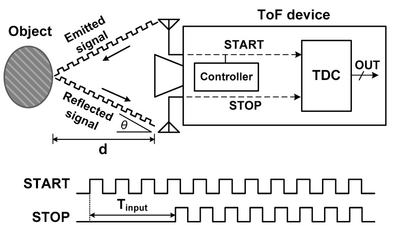
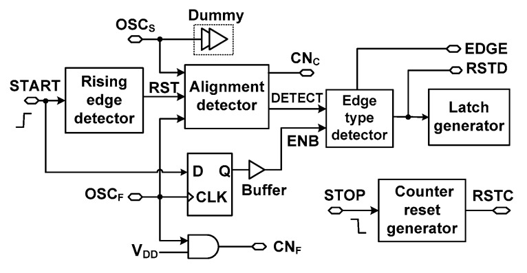
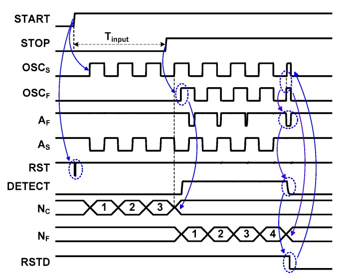
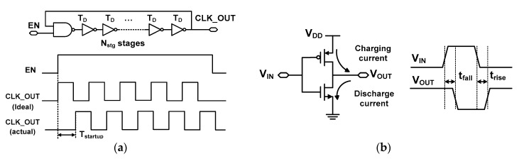
Herein, we present a low-power cyclic Vernier two-step time-to-digital converter (TDC) that achieves a wide input range with good linearity. Since traditional approaches require a large area or high power to achieve an input range >300 ns, we solve this problem by proposing a simple yet efficient TDC suitable for time-of-flight (TOF) sensors. In previous studies using the cyclic structure, the effect of startup time on the linearity of the TDC is not described. Thus, the achievable linearity has been limited when the TDC is used for applications requiring a high input range. We solve this problem by using a simple yet effective technique to compensate. The proposed technique is realized using (1) digitally-controlled oscillators (DCOs) that have dual frequency control and matched startup time; (2) an alignment detector that performs startup time correction by proper timing control; and (3) a fully symmetric arbiter that precisely detects the instant of edge alignment. To achieve a fine resolution for the cyclic Vernier TDC, we design two closely-matched DCOs with dual frequency control. The alignment detector performs the critical task of cancelling startup time via timing control. The detector is delay-compensated by using a dummy to provide matched loading for the two DCOs. To enhance the detection speed under low power, a current-reuse approach is employed for the arbiter. The TDC is fabricated using a 0.18 μm complementary metal–oxide–semiconductor (CMOS) process in a compact chip area of 0.028 mm2. Measured results show a dynamic range of 355 ns and a resolution of 377 ps. When the result is applied for TOF sensing, it corresponds to a distance range of 53.2 m and a resolution of 5.65 cm. Over a relatively large input range, good linearity is achieved, which is indicated by a DNL of 0.28 LSBrms and an INL of 0.96 LSBrms. The result corresponds to root mean square (RMS) error distance of 5.42 cm. The result is achieved by consuming a relatively low power of 0.65 mW.
Overview
The claims and statistics of this paper haven’t been checked yet.
Free: it reads the open-access text and checks the first 5 claims that cite a source we can check. Create a free account to check every claim.
Integrity signals
Registry
Cites
Statistics
Figures


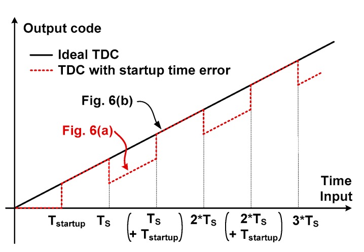
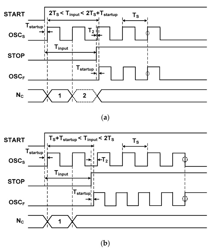


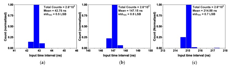
Verification
Claims the paper makes
The claims and statistics of this paper haven’t been checked yet.
Free: it reads the open-access text and checks the first 5 claims that cite a source we can check. Create a free account to check every claim.
Claims other papers make about this one
Each is checked against this paper’s own text: does it say what the citing paper says it does?
The source backs part of the claim, not all of it — or backs it for a different population, condition or comparison.
In the citing paper
“Previously, various TDCs have been suggested to achieve precise time-interval measurements [14][15][16].Yet, they mostly require complex algorithms.”
From A CMOS Optoelectronic Transimpedance Amplifier Using Concurrent Automatic Gain Control for LiDAR Sensors (2024) · cites this paper as [14]
Experimental — accuracy not yet measured
Self-check
Percentages, sums and reported differences re-computed from the paper’s own numbers.
The self-check needs the paper’s full text.
Citations
Cites
CMOS: Circuit Design, Layout, and Simulation
Baker, R. J. (2010) · doi:10.1002/9780470891179 · Cited by 709
Confocal non-line-of-sight imaging based on the light-cone transform
O’Toole, M., Lindell, D. B., & Wetzstein, G. (2018) · Nature · doi:10.1038/nature25489 · Cited by 505 · cited 1×
“In reference [10], a confocal non-line-of-sight (NLOS) imaging technique is presented to address the challenge of reconstructing the shape of hidden objects from extremely weak and multiply scattered light.”
MethodPhoton-efficient imaging with a single-photon camera
Shin, D., Xu, F., Venkatraman, D., Lussana, R., Villa, F., Zappa, F., Goyal, V. K., Wong, F. N. C., & Shapiro, J. H. (2016) · Nature Communications · doi:10.1038/ncomms12046 · Cited by 325
Detection and tracking of moving objects hidden from view
Gariepy, G., Tonolini, F., Henderson, R., Leach, J., & Faccio, D. (2016) · Nature Photonics · doi:10.1038/nphoton.2015.234 · Cited by 278
Henzler, S. (2010) · Springer Series in Advanced Microelectronics · doi:10.1007/978-90-481-8628-0 · Cited by 249
Braga, L. H. C., Gasparini, L., Grant, L., Henderson, R. K., Massari, N., Perenzoni, M., Stoppa, D., & Walker, R. (2014) · IEEE Journal of Solid-State Circuits · doi:10.1109/jssc.2013.2284351 · Cited by 195 · cited 3×
“Compared to other work [23,31], our work achieves an Nlinear of 8.”
BackgroundResultPerenzoni, M., Perenzoni, D., & Stoppa, D. (2017) · IEEE Journal of Solid-State Circuits · doi:10.1109/jssc.2016.2623635 · Cited by 176 · cited 2×
“The time interval between pulse signals is used for various sensing applications, for example, altitude sensing [2], depth sensing [3], respiration rate sensing [4], biomedical image sensing [5,6], and distance sensing for navigation [7].”
MethodNutt, R. (1968) · Review of Scientific Instruments · doi:10.1063/1.1683667 · Cited by 169
Noncontact Respiration Rate Measurement System Using an Ultrasonic Proximity Sensor
Min, S. D., Kim, J. K., Shin, H. S., Yun, Y. H., Lee, C. K., & Lee, M. (2010) · IEEE Sensors Journal · doi:10.1109/jsen.2010.2044239 · Cited by 168 · cited 1×
“The time interval between pulse signals is used for various sensing applications, for example, altitude sensing [2], depth sensing [3], respiration rate sensing [4], biomedical image sensing [5,6], and distance sensing for navigation [7].”
A 100 fps, Time-Correlated Single-Photon-Counting-Based Fluorescence-Lifetime Imager in 130 nm CMOS
Field, R. M., Realov, S., & Shepard, K. L. (2014) · IEEE Journal of Solid-State Circuits · doi:10.1109/jssc.2013.2293777 · Cited by 163 · cited 5×
“[5] [6] [13] [21] [23] [31] [33] This Work”
BackgroundMethodInfluential
Research works printed but not linked: 1
- Wu, 2017, Implementation of a high-precision and wide-range TDC with three-level conversion scheme, IEEE Trans. Circuits Syst. II-Exp. Briefs, 64, 181
Cited by
CMOS Time-to-Digital Converters for Biomedical Imaging Applications
Scott, R., Jiang, W., & Deen, M. J. (2021) · IEEE Reviews in Biomedical Engineering · doi:10.1109/rbme.2021.3092197 · Cited by 39
MATRIX16: A 16-Channel Low-Power TDC ASIC with 8 ps Time Resolution
Mauricio, J., Coromina, L. F., Sanuy, A., Fernandez, S. G., Escalero, R. M., Marin, J., Perez, J. M., Olloqui, E. P., Mendes, P. R., Sánchez, D., et al. (2021) · Electronics · doi:10.3390/electronics10151816 · Cited by 12
Huang, Z., Huang, J., Li, T., Wang, N., Zhu, Y., Wang, H., & Feng, S. (2021) · Sensors · doi:10.3390/s21030743 · Cited by 8
“Generally, D-ToF based 3D image sensor is mainly comprised of two essential modules, respectively the SPAD array and the TDC [32].”
MethodSzyduczyński, J., Kościelnik, D., & Miśkowicz, M. (2019) · Sensors · doi:10.3390/s19051109 · Cited by 11
Technology Independent ASIC Based Time to Digital Converter
Machado, R., Alves, F. S., Geraldes, Á., & Cabral, J. (2020) · IEEE Access · doi:10.1109/access.2020.3034522 · Cited by 5
Metadata
- Authors
- Nguyen, V. N., Duong, D. N., Chung, Y., & Lee, J.-W.
- Affiliations
- Kyung Hee University (KR)
- Corresponding author
- Lee, Jong-Wook
- Venue
- Sensors
- Publisher
- MDPI AG
- Published
- 2018-11-15
- Volume
- 18
- Issue
- 11
- Pages
- 3948
- ISSN
- 1424-8220 (ISSN-L)
- PMC
- PMC6264073
- OpenAlex
- W2901673291
- Cited by
- 15
- References
- 34
- Citations by year
- 2024: 3 · 2023: 1 · 2022: 1 · 2021: 6 · 2020: 2 · 2019: 2
- FWCI
- 0.96
- Type
- journal article
- Language
- en
- Open access
- gold
- dx.doi.org
- Licence
- Locations
- Sensors (publishedVersion, cc-by)
- Europe PMC (PubMed Central) (publishedVersion, other-oa)
- PubMed Central (publishedVersion, cc-by)
- PubMed (publishedVersion)
- DOAJ (DOAJ: Directory of Open Access Journals) (submittedVersion, cc-by-sa)
- Funders
- National Research Foundation of Korea (2018R1A2A2A05018621)
- Topics
- Physical Sciences › Engineering › Electrical and Electronic Engineering › Advancements in PLL and VCO Technologies
- Physical Sciences › Engineering › Electrical and Electronic Engineering › Analog and Mixed-Signal Circuit Design
- Physical Sciences › Engineering › Electrical and Electronic Engineering › Low-power high-performance VLSI design
- Keywords
- time-to-digital converter, time-of-flight sensors, digitally controlled oscillator, current reuse, low power design, wide input voltage range, linearity, distance measurement
About these checks
Registry, retraction, Cites and statistics results are computed, not judged, with one exception: a printed reference that no index lists is read once by a model before it counts as a citation error. Claims are extracted by a model and kept only when their quote appears verbatim in the text; each cited source is then checked, with a model’s help, for whether it says what the claim relies on. Those verdicts can be wrong — read the claim’s quote and the cited source before relying on one.
Statistics and arithmetic are recomputed, not judged.
Confidence bands are shown only for fields calibrated on our annotated test set. None is calibrated yet, so no band is shown.
What counts as a claim ›How we measure confidence ›How we check this ›
Are you an author, or do you see a problem with this page? Request a review
How to cite
Cite CoChat for the checks on this page, and the paper for its own findings.
- This page
- CoChat. (2026). Citation check: A Cyclic Vernier Two-Step TDC for High Input Range Time-of-Flight Sensor Using Startup Time Correction Technique. https://app.cochat.ai/papers/10.3390/s18113948
- The paper
- Nguyen, V. N., Duong, D. N., Chung, Y., & Lee, J.-W. (2018). A Cyclic Vernier Two-Step TDC for High Input Range Time-of-Flight Sensor Using Startup Time Correction Technique. Sensors. https://doi.org/10.3390/s18113948
Data sources
Bibliographic data: Semantic Scholar, OpenAlex, Crossref.
Contains information from the Semantic Scholar Academic Graph Datasets, made available under the ODC Attribution License (ODC-BY 1.0).
Semantic Scholar’s data is described in: Kinney, R., et al. (2023). The Semantic Scholar Open Data Platform. arXiv:2301.10140.
