

The DOI matches its Crossref record; the references it cites are not checked yet.
Screw-Home Movement of the Tibiofemoral Joint during Normal Gait: Three-Dimensional Analysis
Open accessAbstract
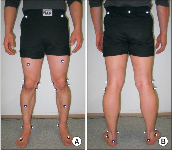
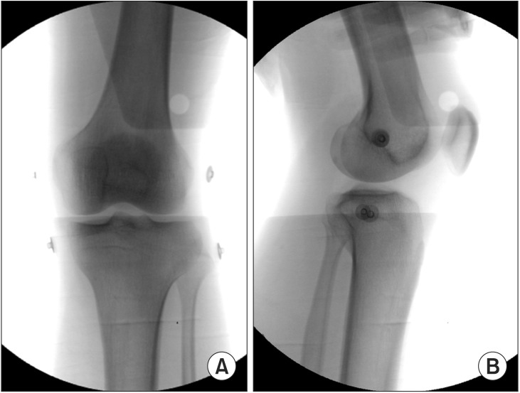
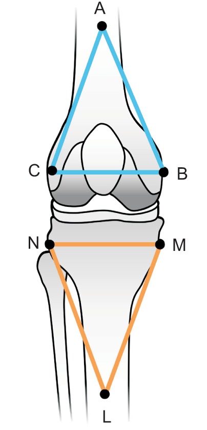
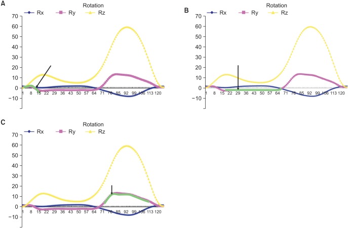
BACKGROUND: The purpose of this study was to evaluate the screw-home movement at the tibiofemoral joint during normal gait by utilizing the 3-dimensional motion capture technique. METHODS: Fifteen young males and fifteen young females (total 60 knee joints) who had no history of musculoskeletal disease or a particular gait problem were included in this study. Two more markers were attached to the subject in addition to the Helen-Hayes marker set. Thus, two virtual planes, femoral coronal plane (P f ) and tibial coronal plane (P t ), were created by Skeletal Builder software. This study measured the 3-dimensional knee joint movement in the sagittal, coronal, and transverse planes of these two virtual planes (P f and P t ) during normal gait. RESULTS: With respect to kinematics and kinetics, both males and females showed normal adult gait patterns, and the mean difference in the temporal gait parameters was not statistically significant (p > 0.05). In the transverse plane, the screw-home movement occurred as expected during the pre-swing phase and the late-swing phase at an angle of about 17°. However, the tibia rotated externally with respect to the femur, rather than internally, while the knee joint started to flex during the loading response (paradoxical screw-home movement), and the angle was 6°. CONCLUSIONS: Paradoxical screw-home movement may be an important mechanism that provides stability to the knee joint during the remaining stance phase. Obtaining the kinematic values of the knee joint during gait can be useful in diagnosing and treating the pathological knee joints.
Overview
The claims and statistics of this paper haven’t been checked yet.
Run the check — free, no account needed. It reads the open-access text and checks the sources it cites.
Integrity signals
Registry
Cites
Statistics
Figures
Verification
Claims the paper makes
The claims and statistics of this paper haven’t been checked yet.
Run the check — free, no account needed. It reads the open-access text and checks the sources it cites.
Self-check
Percentages, sums and reported differences re-computed from the paper’s own numbers.
The self-check needs the paper’s full text.
Citations
The citation lists haven’t been fetched yet
References 21 · Cited by 116
Research works printed but not linked: 21
- Goodfellow, 1978, J Bone Joint Surg Br, 60, 358, 10.1302/0301-620X.60B3.581081 · DOI
- Bytyqi, 2014, Int Orthop, 38, 1191, 10.1007/s00264-014-2312-3 · DOI
- Ishii, 1997, Clin Orthop Relat Res, 144
- Wretenberg, 2002, Clin Biomech (Bristol, Avon), 17, 477, 10.1016/S0268-0033(02)00036-0 · DOI
- Asano, 2001, Clin Orthop Relat Res, 157, 10.1097/00003086-200107000-00023 · DOI
- DeFrate, 2004, J Biomech, 37, 1499, 10.1016/j.jbiomech.2004.01.012 · DOI
- Udagawa, 2014, Am J Sports Med, 42, 2219, 10.1177/0363546514536872 · DOI
- Lee, 2014, Clin Orthop Surg, 6, 117, 10.4055/cios.2014.6.2.117 · DOI
- Yang, 2014, Clin Orthop Surg, 6, 32, 10.4055/cios.2014.6.1.32 · DOI
- Moro-oka, 2007, J Orthop Res, 25, 867, 10.1002/jor.20355 · DOI
- You, 2001, IEEE Trans Med Imaging, 20, 514, 10.1109/42.929617 · DOI
- Komistek, 2003, Clin Orthop Relat Res, 69, 10.1097/01.blo.0000062384.79828.3b · DOI
- Fregly, 2005, J Biomech Eng, 127, 692, 10.1115/1.1933949 · DOI · Paper page
- Moro-oka, 2008, J Orthop Res, 26, 428, 10.1002/jor.20488 · DOI
- Kadaba, 1990, J Orthop Res, 8, 383, 10.1002/jor.1100080310 · DOI · Paper page
- Hill, 2000, J Bone Joint Surg Br, 82, 1196, 10.1302/0301-620X.82B8.10716 · DOI
- Kozanek, 2009, J Biomech, 42, 1877, 10.1016/j.jbiomech.2009.05.003 · DOI
- Qi, 2013, J Biomech, 46, 1576, 10.1016/j.jbiomech.2013.03.014 · DOI
- Koo, 2008, J Biomech, 41, 1269, 10.1016/j.jbiomech.2008.01.013 · DOI
- Karrholm, 2000, J Bone Joint Surg Br, 82, 1201, 10.1302/0301-620X.82B8.10715 · DOI
- Lafortune, 1992, J Biomech, 25, 347, 10.1016/0021-9290(92)90254-X · DOI
Metadata
- Authors
- Kim, H. Y., Kim, K. J., Yang, D. S., Jeung, S. W., Choi, H. G., & Choy, W. S.
- Affiliations
- Department of Orthopedic Surgery, Eulji University College of Medicine, Daejeon, Korea.
- Eulji University (KR)
- Corresponding author
- Kim, Kap Jung
- Venue
- Clinics in Orthopedic Surgery
- Publisher
- XMLink
- Published
- 2015
- Volume
- 7
- Issue
- 3
- Pages
- 303
- ISSN
- 2005-291X (ISSN-L)
- 2005-4408
- PMC
- PMC4553277
- OpenAlex
- W1634072844
- Cited by
- 116
- References
- 21
- Citations by year
- 2026: 9 · 2025: 15 · 2024: 15 · 2023: 21 · 2022: 11 · 2021: 14 · 2020: 11 · 2019: 8 · 2018: 6 · 2017: 5 · 2016: 1
- FWCI
- 1.87
- Type
- journal article
- Language
- en
- Open access
- diamond
- doi.org
- Licence
- Locations
- Clinics in Orthopedic Surgery (publishedVersion, cc-by-nc)
- PubMed Central (publishedVersion, cc-by-nc)
- PubMed (publishedVersion)
- Topics
- Physical Sciences › Engineering › Biomedical Engineering › Lower Extremity Biomechanics and Pathologies
- Health Sciences › Medicine › Surgery › Knee injuries and reconstruction techniques
- Health Sciences › Medicine › Surgery › Total Knee Arthroplasty Outcomes
- Keywords
- tibiofemoral joint, knee kinematics, normal gait, tibial external rotation, knee stability, loading response, sex differences in gait
- MeSH terms
- Adolescent, Adult, Biomechanical Phenomena, Female, Gait, Humans, Knee Joint, Male, Sex Factors, Range of Motion, Articular, Walking, Imaging, Three-Dimensional, Young Adult, Fiducial Markers
About these checks
Registry, retraction, Cites and statistics results are computed, not judged, with one exception: a printed reference that no index lists is read once by a model before it counts as a citation error. Claims are extracted by a model and kept only when their quote appears verbatim in the text; each cited source is then checked, with a model’s help, for whether it says what the claim relies on. Those verdicts can be wrong — read the claim’s quote and the cited source before relying on one.
Statistics and arithmetic are recomputed, not judged.
Confidence bands are shown only for fields calibrated on our annotated test set. None is calibrated yet, so no band is shown.
What counts as a claim ›How we measure confidence ›How we check this ›
Are you an author, or do you see a problem with this page? Request a review
How to cite
Cite CoChat for the checks on this page, and the paper for its own findings.
- This page
- CoChat. (2026). Citation check: Screw-Home Movement of the Tibiofemoral Joint during Normal Gait: Three-Dimensional Analysis. https://app.cochat.ai/papers/10.4055/cios.2015.7.3.303
- The paper
- Kim, H. Y., Kim, K. J., Yang, D. S., Jeung, S. W., Choi, H. G., & Choy, W. S. (2015). Screw-Home Movement of the Tibiofemoral Joint during Normal Gait: Three-Dimensional Analysis. Clinics in Orthopedic Surgery. https://doi.org/10.4055/cios.2015.7.3.303
