

The DOI matches its Crossref record; 31 of the 31 references it cites were found in a registry or an index.
A lightweight magnetically shielded room with active shielding
Open accessAbstract
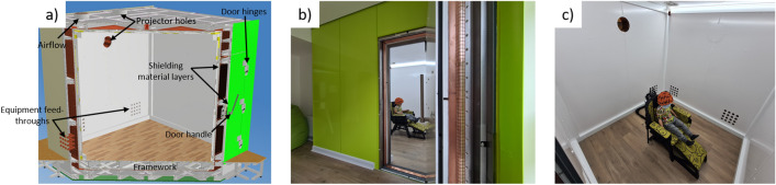
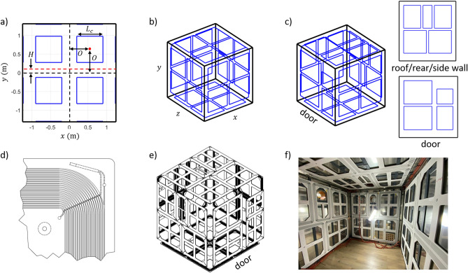
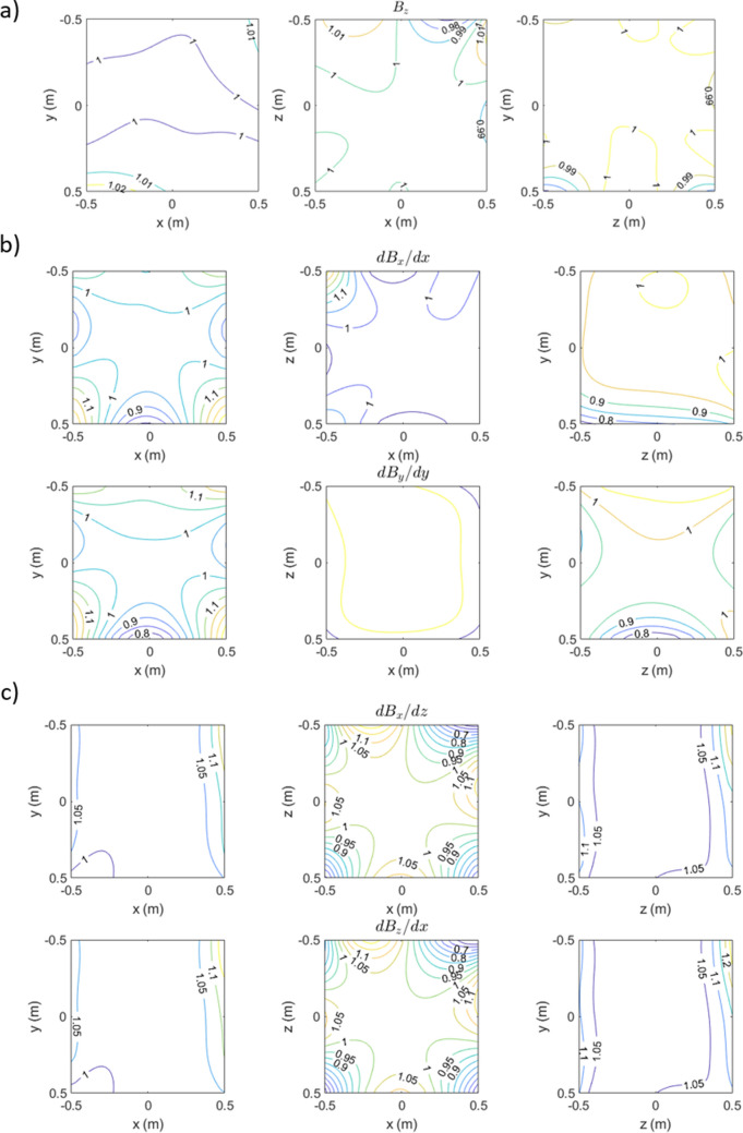
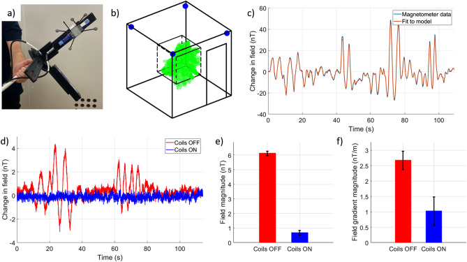
Magnetically shielded rooms (MSRs) use multiple layers of materials such as MuMetal to screen external magnetic fields that would otherwise interfere with high precision magnetic field measurements such as magnetoencephalography (MEG). Optically pumped magnetometers (OPMs) have enabled the development of wearable MEG systems which have the potential to provide a motion tolerant functional brain imaging system with high spatiotemporal resolution. Despite significant promise, OPMs impose stringent magnetic shielding requirements, operating around a zero magnetic field resonance within a dynamic range of ± 5 nT. MSRs developed for OPM-MEG must therefore effectively shield external sources and provide a low remnant magnetic field inside the enclosure. Existing MSRs optimised for OPM-MEG are expensive, heavy, and difficult to site. Electromagnetic coils are used to further cancel the remnant field inside the MSR enabling participant movements during OPM-MEG, but present coil systems are challenging to engineer and occupy space in the MSR limiting participant movements and negatively impacting patient experience. Here we present a lightweight MSR design (30% reduction in weight and 40–60% reduction in external dimensions compared to a standard OPM-optimised MSR) which takes significant steps towards addressing these barriers. We also designed a ‘window coil’ active shielding system, featuring a series of simple rectangular coils placed directly onto the walls of the MSR. By mapping the remnant magnetic field inside the MSR, and the magnetic field produced by the coils, we can identify optimal coil currents and cancel the remnant magnetic field over the central cubic metre to just |B|= 670 ± 160 pT. These advances reduce the cost, installation time and siting restrictions of MSRs which will be essential for the widespread deployment of OPM-MEG.
Overview
The claims and statistics of this paper haven’t been checked yet.
Run the check — free, no account needed. It reads the open-access text and checks the sources it cites.
Integrity signals
Registry
Cites
Statistics
Figures
Verification
Claims the paper makes
The claims and statistics of this paper haven’t been checked yet.
Run the check — free, no account needed. It reads the open-access text and checks the sources it cites.
Claims other papers make about this one
Each is checked against this paper’s own text: does it say what the citing paper says it does?
The cited source says what the claim attributes to it.
In the citing paper
“These constraints mean that OPM-MEG experiments involving participant motion require an OPM-optimised MSR with a very low remnant magnetic field along with ‘active’ magnetic shielding”
From Naturalistic Hyperscanning with Wearable Magnetoencephalography (2023) · cites this paper as [38]
Self-check
Percentages, sums and reported differences re-computed from the paper’s own numbers.
The self-check needs the paper’s full text.
Citations
Cites
Hämäläinen, M., Hari, R., Ilmoniemi, R. J., Knuutila, J., & Lounasmaa, O. V. (1993) · Reviews of Modern Physics · doi:10.1103/revmodphys.65.413 · Cited by 4,684
Moving magnetoencephalography towards real-world applications with a wearable system
Boto, E., Holmes, N., Leggett, J., Roberts, G., Shah, V., Meyer, S. S., Muñoz, L. D., Mullinger, K. J., Tierney, T. M., Bestmann, S., et al. (2018) · Nature · doi:10.1038/nature26147 · Cited by 1,377
Self-citationHigh-Sensitivity Atomic Magnetometer Unaffected by Spin-Exchange Relaxation
Allred, J. C., Lyman, R. N., Kornack, T. W., & Romalis, M. V. (2002) · Physical Review Letters · doi:10.1103/physrevlett.89.130801 · Cited by 1,049
Magnetoencephalography for Brain Electrophysiology and Imaging
Baillet, S. (2017) · Nature Neuroscience · doi:10.1038/nn.4504 · Cited by 992
Magnetoencephalography: Evidence of Magnetic Fields Produced by Alpha-Rhythm Currents
Cohen, D. (1968) · Science · doi:10.1126/science.161.3843.784 · Cited by 750
A compact, high performance atomic magnetometer for biomedical applications
Shah, V. K., & Wakai, R. T. (2013) · Physics in Medicine and Biology · doi:10.1088/0031-9155/58/22/8153 · Cited by 322
Self-citationMulti-Channel Whole-Head OPM-MEG: Helmet Design and a Comparison with a Conventional System
Hill, R. M., Boto, E., Rea, M., Holmes, N., Leggett, J., Coles, L. A., Papastavrou, M., Everton, S. K., Hunt, B. A. E., Sims, D., et al. (2020) · NeuroImage · doi:10.1016/j.neuroimage.2020.116995 · Cited by 285
Self-citationOn-scalp MEG system utilizing an actively shielded array of optically-pumped magnetometers
Iivanainen, J., Zetter, R., Grön, M., Hakkarainen, K., & Parkkonen, L. (2019) · NeuroImage · doi:10.1016/j.neuroimage.2019.03.022 · Cited by 269
Holmes, N., Leggett, J., Boto, E., Roberts, G., Hill, R. M., Tierney, T. M., Shah, V., Barnes, G. R., Brookes, M. J., & Bowtell, R. (2018) · NeuroImage · doi:10.1016/j.neuroimage.2018.07.028 · Cited by 250
Self-citationDetection of very weak magnetic fields (10−9gauss) by 87Rb zero-field level crossing resonances
Dupont-Roc, J., Haroche, S., & Cohen-Tannoudji, C. N. (1969) · Physics Letters A · doi:10.1016/0375-9601(69)90480-0 · Cited by 180
Research works printed but not linked: 1
- Juhas, A., Pekari, N. & Toepfer, H. Magnetic field of rectangular current loop with sides parallel and perpendicular to the surface of high-permeability material. SJEE 11, 701–717 (2014).
Cited by
Sorted by citations
Items 101–128 of 128
Liu, J., Wu, H., Yang, Z., Zhao, J., Chen, X., Cui, P., & Zheng, S. (2025) · Journal of Applied Physics · doi:10.1063/5.0289802
Qiu, S., Tang, J., Tian, P., & Zhao, F. (2025) · IEEE Transactions on Instrumentation and Measurement · doi:10.1109/tim.2025.3648094
Honglin, Y., Zhang, X., Ding, F., Xu, C., Wu, S., Yuan, X., & Zhou, H. (2026) · Physica Scripta · doi:10.1088/1402-4896/ae32cd
Liu, Y., Xu, X., & Han, C. (2026) · Journal of Physics D Applied Physics · doi:10.1088/1361-6463/ae39e8
Sun, Q., Wu, Z., Tang, W., & Liu, Z. (2025) · International Conference on Intelligent Communication, Sensing and Electromagnetics (ICSE) · doi:10.1109/icse68658.2025.11407647
Simulating tailored nulling coils for inhomogeneous magnetic fields in a cylindrical mu-metal shield
Leslie, C. D., Hess, A. I. T., Holmes, N., & Bardouille, T. (2026) · Results in Physics · doi:10.1016/j.rinp.2026.108631
Self-citationRealising the potential of wearable magnetoencephalography
Rivero, G. R. (2025) · Nottingham ePrints (University of Nottingham) · doi:10.17639/11303
A corrected image method for uniform coil design with size adaptability in magnetic shielding rooms
Sun, J., Shi, Y., Gan, Z., Zhou, W., Feng, S., & Han, B. (2026) · Measurement · doi:10.1016/j.measurement.2026.121314
Experimental setup for the combined study of spin ensembles and superconducting quantum circuits
Vogl, L., Huber, G. B. P., Strinić, A., Marx, A., Filipp, S., Fedorov, K. G., Groß, R., & Kukharchyk, N. (2026) · Cryogenics · doi:10.1016/j.cryogenics.2026.104378
Atomic magnetometry based on the ground-state Hanle effect in an elliptically polarized light wave
Brazhnikov, D. V., Makarov, A., Kozlova, K., & Goncharov, A. (2026) · The European Physical Journal D · doi:10.1140/epjd/s10053-026-01170-7
Multi-Layer Magnetic Shields Based on Fe-Based Nanocrystalline and Co-Based Amorphous Ribbons
Liang, Y., Liu, B., Ma, H. F., Pan, L., He, A., Dong, Y., Man, Q., & Li, J. (2026) · Materials · doi:10.3390/ma19101986
Hybrid Optimal Design of External Compensation Coils of Magnetic Shielding Room
Yang, Z., Cui, P., Jia, L., & Li, Y. (2026) · Journal of Physics Conference Series · doi:10.1088/1742-6596/3249/1/012017
Sun, J., Sun, H., Chen, D., Xie, X., Jiang, Q., & Ye, J. (2026) · Measurement Science and Technology · doi:10.1088/1361-6501/ae7aa2
Cao, X., Zhu, T., Chikaki, S., Fushimi, M., & Sekino, M. (2026) · IEEE Transactions on Instrumentation and Measurement · doi:10.1109/tim.2026.3701193
Static behavior of aluminum gusset joints with titanium bolts for reticulated shells
Wu, B., Zhang, Y., & Cao, Z. (2026) · Journal of Constructional Steel Research · doi:10.1016/j.jcsr.2026.110559
Sun, J., Shi, Y., Ji, A., Feng, S., & Zhou, W. (2026) · Youth Academic Annual Conference of Chinese Association of Automation (YAC) · doi:10.1109/yac71005.2026.11616013
Wang, W., Tang, J., Zhao, F., Chen, Y., Shangguan, S., & Qiu, S. (2026) · Measurement · doi:10.1016/j.measurement.2026.122823
Liu, S., Watts, M., Diver, C., Ang, D., Meisenhelder, C., Fan, X., Hao, B., Lascar, D., Hiramoto, A., Masuda, T., et al. (2026) · arXiv (Cornell University) · doi:10.48550/arxiv.2608.11439
A Dual-Chip-Based NV-Center Magnetometer With Integrated Microwave Generation and Optical Readout
Khan, K., Hengel, P., Kern, M., Peng, Y., Buchau, A., Schmitt, L., Fuchs, T., Wrachtrup, J., & Anders, J. (2026) · IEEE Journal of Solid-State Circuits · doi:10.1109/jssc.2026.3724738
Opportunities for Quantum Sensing in Epilepsy Diagnostics
Kalinina, D., Pak, A., Dossov, M., Utebekov, Z., Kyrgyzbay, G., Kimadiev, D., Zhumabayeva, G., Hernandez, F. U., & Berengueres, J. O. L. (2026) · Sensors · doi:10.3390/s26175490
Rehbein, M. A., Kroker, T., Wollbrink, A., & Junghoefer, M. (2026) · Neuromethods · doi:10.1007/978-1-0716-5340-1_6
Shangguan, S., Han, B., Zhao, X., Chen, Y., & Feng, R. (2026) · Measurement · doi:10.1016/j.measurement.2026.123173
Zhao, Z. (2026) · SSRN Electronic Journal · doi:10.2139/ssrn.7631698
Xu, X., Zhang, X., Han, C., & Liu, Y. (2026) · IEEE Transactions on Instrumentation and Measurement · doi:10.1109/tim.2026.3743998
Embury, C. M., Seedat, Z. A., Pier, K. S., Scott, C., Tierney, T. M., Vivekananda, U., Moeller, F., Das, K., Barnes, G. R., Tewarie, P. K. B., et al. (2026) · Clinical Neurophysiology · doi:10.1016/j.clinph.2026.2112443
Self-citationWang, H., Shi, M., Deng, Y., Li, T., Zhang, L., Ma, Y., & Li, Y. (2026) · Measurement · doi:10.1016/j.measurement.2026.123629
Greentree, A. D., Johnstone, T., Kealy, A., Sun, Q., & White, D. (2026) · Health Policy and Technology · doi:10.1016/j.hlpt.2026.101357
Peng, Y., & Ding, M. L. (2026) · Brain Sciences · doi:10.3390/brainsci16111217
Metadata
- Authors
- Holmes, N., Rea, M., Chalmers, J., Leggett, J., Edwards, L. J., Nell, P., Pink, S., Patel, P., Wood, J., Murby, N., Woolger, D., Dawson, E., Mariani, C., Tierney, T. M., Mellor, S., O’Neill, G. C., Boto, E., Hill, R. M., Shah, V., Osborne, J., Pardington, R., Fierlinger, P., Barnes, G. R., Glover, P., Brookes, M. J., & Bowtell, R.
- Affiliations
- University of Nottingham (GB)
- Wellcome Centre for Human Neuroimaging (GB)
- QuSpin (United States) (US)
- Technical University of Munich (DE)
- Corresponding author
- Holmes, Niall
- ORCID
- Venue
- Scientific Reports
- Published
- 2022-08-09
- Volume
- 12
- Issue
- 1
- Pages
- 13561-13561
- ISSN
- 2045-2322 (ISSN-L)
- PMC
- PMC9363499
- OpenAlex
- W4291020559
- Cited by
- 121
- References
- 31
- Citations by year
- 2026: 24 · 2025: 39 · 2024: 34 · 2023: 22 · 2022: 2
- FWCI
- 9.95
- Type
- journal article
- Language
- en
- Open access
- gold
- doi.org
- Locations
- Scientific Reports (publishedVersion, cc-by)
- PubMed Central (publishedVersion, cc-by)
- PubMed (publishedVersion)
- Repository@Nottingham (University of Nottingham) (publishedVersion, other-oa)
- Repository@Nottingham (University of Nottingham) (submittedVersion, cc-by)
- DOAJ (DOAJ: Directory of Open Access Journals) (submittedVersion, cc-by-sa)
- UCL Discovery (University College London) (submittedVersion)
- mediaTUM – the media and publications repository of the Technical University Munich (Technical University Munich) (submittedVersion, other-oa)
- Funders
- Engineering and Physical Sciences Research Council (EP/T001046/1)
- Innovate UK (104604)
- Wellcome Trust (203257/Z/16/Z)
- Topics
- Physical Sciences › Physics and Astronomy › Atomic and Molecular Physics, and Optics › Atomic and Subatomic Physics Research
- Physical Sciences › Engineering › Electrical and Electronic Engineering › Electromagnetic Compatibility and Measurements
- Physical Sciences › Engineering › Biomedical Engineering › Characterization and Applications of Magnetic Nanoparticles
- Keywords
- magnetically shielded room, active magnetic shielding, optically pumped magnetometers, mu-metal, electromagnetic coils
- MeSH terms
- Brain, Humans, Magnetic Resonance Imaging, Magnetic Resonance Spectroscopy, Magnetoencephalography, Functional Neuroimaging, Magnetic Fields
About these checks
Registry, retraction, Cites and statistics results are computed, not judged, with one exception: a printed reference that no index lists is read once by a model before it counts as a citation error. Claims are extracted by a model and kept only when their quote appears verbatim in the text; each cited source is then checked, with a model’s help, for whether it says what the claim relies on. Those verdicts can be wrong — read the claim’s quote and the cited source before relying on one.
Statistics and arithmetic are recomputed, not judged.
Confidence bands are shown only for fields calibrated on our annotated test set. None is calibrated yet, so no band is shown.
What counts as a claim ›How we measure confidence ›How we check this ›
Are you an author, or do you see a problem with this page? Request a review
