

The DOI matches its Crossref record; 4 of the 4 references it cites were found in a registry or an index.
Optical spin–orbit coupling in the presence of magnetization: photonic skyrmion interaction with magnetic domains
Abstract
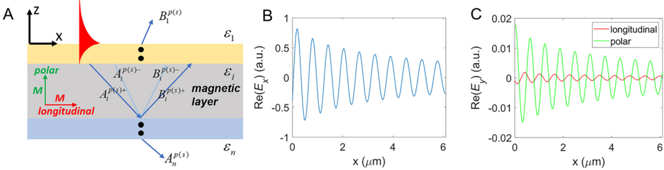
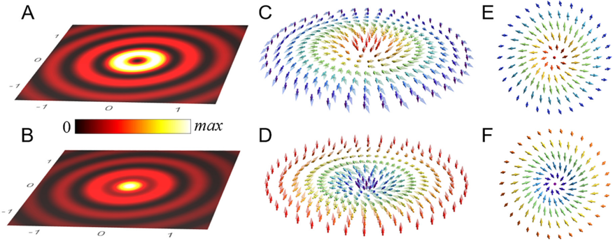
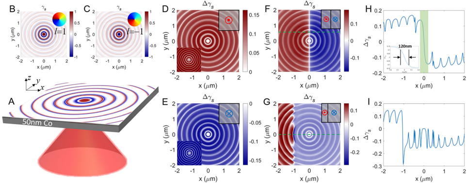
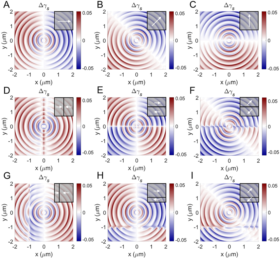
Polarization and related spin properties are important characteristics of electromagnetic waves and their manipulation is crucial in almost all photonic applications. Magnetic materials are often used for controlling light polarization through the magneto‐optical Kerr or Faraday effects. Recently, complex topological structures of the optical spin have been demonstrated in the evanescent light field, which in the presence of the spin–orbit coupling may form photonic skyrmions. Here, we investigate the optical spin–orbit coupling in the presence of magnetization and the interaction between photonic skyrmions and magnetic domains. We demonstrate that the magnetization is responsible for the modulation of the optical spin distribution, resulting in twisted Neel‐type skyrmions. This effect can be used for the visualization of magnetic domain structure with both in plane and polar orientation of magnetization, and in turn for creation of complex optical spin distributions using magnetization patterns. The demonstrated interplay between photonic skyrmions and magneto‐optical effects may also provide novel opportunities for investigation and manipulation of magnetic skyrmions using optical spin–orbit coupling.
Overview
The claims and statistics of this paper haven’t been checked yet.
Run the check — free, no account needed. It reads the open-access text and checks the sources it cites.
Integrity signals
Registry
Cites
Statistics
Figures
Verification
Claims the paper makes
The claims and statistics of this paper haven’t been checked yet.
Run the check — free, no account needed. It reads the open-access text and checks the sources it cites.
Claims other papers make about this one
Each is checked against this paper’s own text: does it say what the citing paper says it does?
The check wasn’t confident either way, so it gives no verdict — never disputed.
In the citing paper
“The above topological classification is also applicable to merons and bimerons [35,36] (Fig. 2).”
From Optical skyrmions and other topological quasiparticles of light (2024) · cites this paper as [36]
Experimental — accuracy not yet measured
Self-check
Percentages, sums and reported differences re-computed from the paper’s own numbers.
The self-check needs the paper’s full text.
Citations
Cites
Spin–orbit interactions of light
Bliokh, K. Y., Rodríguez-Fortuño, F. J., Nori, F., & Zayats, A. V. (2015) · Nature Photonics · doi:10.1038/nphoton.2015.201 · Cited by 2,276
Self-citationOptical skyrmion lattice in evanescent electromagnetic fields
Tsesses, S., Ostrovsky, E., Cohen, K., Gjonaj, B., Lindner, N. H., & Bartal, G. (2018) · Science · doi:10.1126/science.aau0227 · Cited by 514
Transverse spin of a surface polariton
Bliokh, K. Y., & Nori, F. (2012) · Physical Review A · doi:10.1103/physreva.85.061801 · Cited by 364
Spin-orbit interactions of light
Bliokh, K. Y., Rodriguez-Fortuno, F. J., Nori, F., & Zayats, A. V. (2015) · arXiv
Self-citation
Research works printed but not linked: 46
- 10.1038/nature09124 · DOI
- 10.1126/science.1240573 · DOI
- 10.1016/0304‐8853(86)90044‐2 · DOI
- 10.1109/tnano.2004.837850 · DOI
- 10.1002/9780470022184.hmm310 · DOI
- 10.1088/0022‐3727/48/33/333001 · DOI
- Hubert A., 2008, Magnetic Domains: The Analysis of Magnetic Microstructures
- 10.1103/PhysRevB.64.235422 · DOI
- 10.1103/physrevlett.91.183901 · DOI
- 10.1103/PhysRevB.76.153402 · DOI
- 10.1002/adom.201801420 · DOI
- 10.1103/physrevlett.104.147401 · DOI
- 10.1038/nnano.2011.54 · DOI
- 10.1002/adom.201200011 · DOI
- Kreilkamp L. E., 2013, “Waveguide‐plasmon polaritons enhance transverse magneto‐optical Kerr effect,”, Phys. Rev. X, 3, 041019
- 10.1021/acsphotonics.5b00490 · DOI
- 10.1038/s41567‐019‐0487‐7 · DOI · Paper page
- X.Lei A.Yang P.Shi et al. “Photonic spin lattices: symmetry constraints for skyrmion and meron topologies ”arXiv preprint arXiv:2103.15366 2021. · DOI · Paper page
- 10.1887/0750309016 · DOI · Paper page
- 10.1103/PhysRevLett.88.053601 · DOI · Paper page
- 10.1088/1464-4266/4/2/361 · DOI
- 10.1088/2040‐8978/13/5/053001 · DOI · Paper page
- 10.1126/science.1257671 · DOI · Paper page
- 10.1038/ncomms6327 · DOI · Paper page
- 10.1126/science.aaa9519 · DOI · Paper page
- 10.1364/optica.3.000118 · DOI
- 10.1126/science.1233739 · DOI · Paper page
- 10.1038/ncomms10051 · DOI
- 10.1103/physrevlett.121.193901 · DOI
- 10.1103/revmodphys.82.3045 · DOI · Paper page
- 10.1038/ncomms4300 · DOI · Paper page
- 10.1038/nphoton.2015.203 · DOI
- 10.1038/nphoton.2009.265 · DOI
- 10.1063/1.3512874 · DOI
- 10.1364/josa.62.000502 · DOI
- 10.1364/josa.64.000166 · DOI
- 10.1016/0039‐6028(80)90293‐9 · DOI
- 10.1016/0304‐8853(90)90713‐z · DOI
- 10.1364/oe.9.000121 · DOI
- 10.1103/physrevb.9.5056 · DOI
- 10.1887/075030362X · DOI
- 10.1002/9781119079699 · DOI
- 10.1038/nnano.2013.243 · DOI
- 10.1073/pnas.2018816118 · DOI · Paper page
- 10.1103/PhysRevB.87.094424 · DOI
- 10.1103/physrevlett.120.227202 · DOI
Cited by
Sorted by citations
Optical skyrmions and other topological quasiparticles of light
Shen, Y., Zhang, Q., Shi, P., Du, L., Yuan, X., & Zayats, A. V. (2024) · Nature Photonics · doi:10.1038/s41566-023-01325-7 · Cited by 469
Self-citationTopological state and number transitions of optical skyrmions upon free-space beam propagation
Fan, X., Wu, X., Ren, K., Zhou, L., Guo, X., Wei, B., Zhang, Y., Liu, S., Li, P., & Zhao, J. (2025) · Communications Physics · doi:10.1038/s42005-025-02427-0 · Cited by 2
Metadata
- Authors
- Lei, X., Du, L., Yuan, X., & Zayats, A. V.
- Venue
- Nanophotonics
- Publisher
- Wiley
- Published
- 2021-08-24
- Volume
- 10
- Issue
- 14
- Pages
- 3667-3675
- ISSN
- 2192-8614
- Cited by
- 69
- References
- 4
- Language
- en
- Funders
- Natural Science Foundation of Guangdong Province (2016A030312010)
- National Natural Science Foundation of China (61427819, 61622504, 61705135, 61935013, 62075139, U1701661)
- Shenzhen Peacock Plan (KQTD2015071016560101, KQTD20170330110444030)
About these checks
Registry, retraction, Cites and statistics results are computed, not judged, with one exception: a printed reference that no index lists is read once by a model before it counts as a citation error. Claims are extracted by a model and kept only when their quote appears verbatim in the text; each cited source is then checked, with a model’s help, for whether it says what the claim relies on. Those verdicts can be wrong — read the claim’s quote and the cited source before relying on one.
Statistics and arithmetic are recomputed, not judged.
Confidence bands are shown only for fields calibrated on our annotated test set. None is calibrated yet, so no band is shown.
What counts as a claim ›How we measure confidence ›How we check this ›
Are you an author, or do you see a problem with this page? Request a review
