CoChat

Exceptional Cases Demand Exceptional Personalized Solutions: The Next Level in Dental Rehabilitation

Open access

The DOI matches its Crossref record; 32 of the 32 references it cites were found in a registry or an index.

Abstract

Defects and bone loss in the maxilla and mandible pose significant challenges for dental rehabilitation. This paper focuses on complex cases of bimaxillary dental rehabilitation, where traditional dental implant protocols were not feasible in at least one jaw. Four patients were examined conceptually, where conventional dental implant placement (n = 20) was combined in either the same or opposite jaw with a patient-specific subperiosteal implant (n = 5). This study evaluates aspects such as primary stability, prosthodontic restoration, complications, and soft tissue management over the observation period. None of the five patient-specific subperiosteal implants (IPS Implants® Preprosthetic; KLS-Martin Group, Tuttlingen, Germany) experienced failure or showed any loosening of screws, with the longest observation period extending to 68 months. These implants were securely fixated away from the posts, without any biomechanical restrictions on loading from the time of insertion. Planning and manufacturing, including the initial suprastructure, followed a fully digital workflow. The number of screws required for multivector fixation ranged from 13 to 22. All dental implants placed remain functional, definitive prosthodontic restoration has been performed, and no stability loss or peri-implantitis has been observed. The IPS Implants® Preprosthetic emerges as a valuable consideration when conventional implant dentistry protocols encounter limitations.

Overview

The claims and statistics of this paper haven’t been checked yet.

Free: it reads the open-access text and checks the first 5 claims that cite a source we can check. Create a free account to check every claim.

A few free checks a day · papers already verified open instantly · results are public

Integrity signals

Registry

Crossref · 10.3390/jpm14030294

Cites

32 of 32 references verified0 citation errors · 0 not checkable

Statistics

Figures

Figure 1 (a–c): En face view reveals deepened nasolabial folds and a typical pseudo-class III relationship resulting from severe maxillary atrophy. Intraorally, healthy but reduced tissues are observed in the edentulous maxilla and mandible. Two telescoping crowns are present on two out of three mandibular dental implants, which were previously placed elsewhere.
Figure 1 (a–c): En face view reveals deepened nasolabial folds and a typical pseudo-class III relationship resulting from severe maxillary atrophy. Intraorally, healthy but reduced tissues are observed in the edentulous maxilla and mandible. Two telescoping crowns are present on two out of three mandibular dental implants, which were previously placed elsewhere.CC BY · PubMed Central
Figure 2 (a–c): Three cone-beam coronal views from the same patient in Figure 1 depict the reduced horizontal and vertical bone stock in the edentulous maxilla, displaying typical sequelae of atrophy-related centripetal bone loss.
Figure 2 (a–c): Three cone-beam coronal views from the same patient in Figure 1 depict the reduced horizontal and vertical bone stock in the edentulous maxilla, displaying typical sequelae of atrophy-related centripetal bone loss.CC BY · PubMed Central
Figure 3 (a–d): Four screenshots from the case designer (KLS Martin-Group, Tuttlingen, Germany) display the one-piece subperiosteal implant (a). A red subvolume is delineated bilaterally in the atrophic maxilla, indicating a planned marginal bone resection (a–d). Four implant posts are deemed adequate to withstand occlusal forces in the edentulous maxilla (similar considerations apply to the mandible). Superimposition with the scanned pre-existing overdentures is depicted in (c,d), facilitating assessment of the implant-borne prosthodontic compensation for the skeletal pseudo-class III; this naturally requires intact intra- and extraoral soft tissues.
Figure 3 (a–d): Four screenshots from the case designer (KLS Martin-Group, Tuttlingen, Germany) display the one-piece subperiosteal implant (a). A red subvolume is delineated bilaterally in the atrophic maxilla, indicating a planned marginal bone resection (a–d). Four implant posts are deemed adequate to withstand occlusal forces in the edentulous maxilla (similar considerations apply to the mandible). Superimposition with the scanned pre-existing overdentures is depicted in (c,d), facilitating assessment of the implant-borne prosthodontic compensation for the skeletal pseudo-class III; this naturally requires intact intra- and extraoral soft tissues.CC BY · PubMed Central
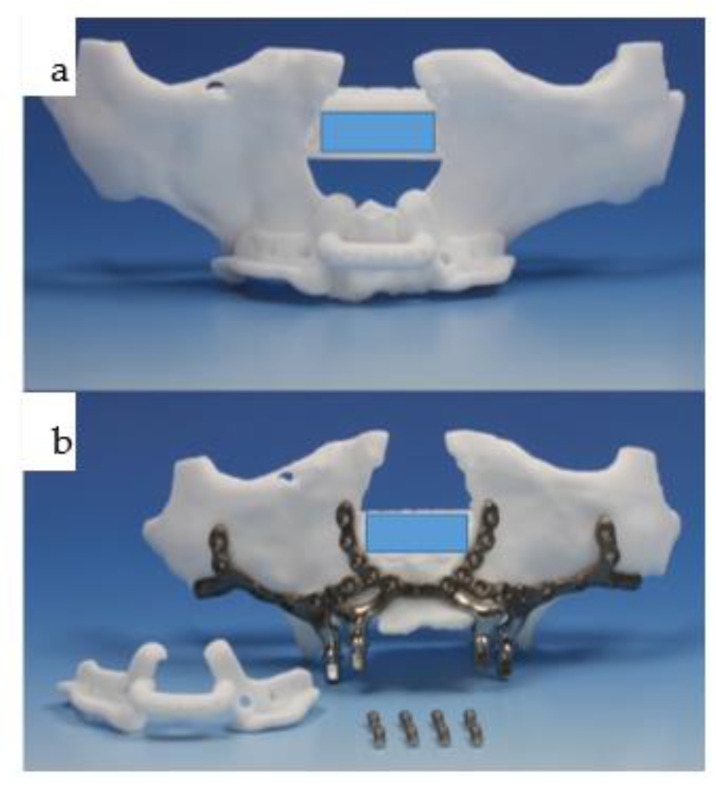
Figure 4 (a,b): The polyamide resection template is affixed to the patient’s biomodel in (a), featuring two extensions at the piriform aperture toward the nasal floor to ensure a one-fit-only design. Holes are provided for potential bony anchorage via screw fixation (note: due to the perfect fit, these holes have not been utilized by the authors thus far). The IPS Implants® Preprosthetic (KLS Martin-Group, Tuttlingen, Germany) was then placed onto the biomodel, incorporating the intended bone resection in the maxilla, allowing the one-piece subperiosteal implant (b) to fit seamlessly into the bilateral marginal alveolar crest resection. In addition to the resection template, two sets of prosthodontic screws (four each) are visible: only four are necessary to secure the initial provisional suprastructure at the time of surgery and beyond, until the final prosthesis is fabricated.
Figure 4 (a,b): The polyamide resection template is affixed to the patient’s biomodel in (a), featuring two extensions at the piriform aperture toward the nasal floor to ensure a one-fit-only design. Holes are provided for potential bony anchorage via screw fixation (note: due to the perfect fit, these holes have not been utilized by the authors thus far). The IPS Implants® Preprosthetic (KLS Martin-Group, Tuttlingen, Germany) was then placed onto the biomodel, incorporating the intended bone resection in the maxilla, allowing the one-piece subperiosteal implant (b) to fit seamlessly into the bilateral marginal alveolar crest resection. In addition to the resection template, two sets of prosthodontic screws (four each) are visible: only four are necessary to secure the initial provisional suprastructure at the time of surgery and beyond, until the final prosthesis is fabricated.CC BY · PubMed Central
Figure 5 (a–d): Four orthopantomograms depict the dental rehabilitation sequence, commencing with the insertion of the IPS Implants® Preprosthetic (KLS Martin-Group, Tuttlingen, Germany) (a); subsequently, the positions for the three bone-level tapered implants were drilled in a 3D-guided manner in a second step (b). During recall, the final bar-retained suprastructure (c) is visible, as well as at the three-year follow-up (d). No bone loss or screw loosening is evident. The key distinction between conventional implants and IPS Implants® Preprosthetic anchorage is apparent: unlike conventional implants, where anchorage relies on multivector screw-based fixation near the area equivalent to the dental implant shoulder, the IPS Implants® Preprosthetic constitutes a one-piece implant with a rotationally stable telescoping abutment component.
Figure 5 (a–d): Four orthopantomograms depict the dental rehabilitation sequence, commencing with the insertion of the IPS Implants® Preprosthetic (KLS Martin-Group, Tuttlingen, Germany) (a); subsequently, the positions for the three bone-level tapered implants were drilled in a 3D-guided manner in a second step (b). During recall, the final bar-retained suprastructure (c) is visible, as well as at the three-year follow-up (d). No bone loss or screw loosening is evident. The key distinction between conventional implants and IPS Implants® Preprosthetic anchorage is apparent: unlike conventional implants, where anchorage relies on multivector screw-based fixation near the area equivalent to the dental implant shoulder, the IPS Implants® Preprosthetic constitutes a one-piece implant with a rotationally stable telescoping abutment component.CC BY · PubMed Central
Figure 6 (a–f): Six intraoperative views illustrate the sequencing of IPS Implants® Preprosthetic (KLS Martin-Group, Tuttlingen, Germany) insertion: first, the mucoperiosteal flap is harvested from the posterior right to left maxilla, with a small (1.2 cm) bilateral posterior vestibular periosteal release incision (a); next, piezosurgery is utilized for marginal bone resection on the right (b) and left (c) maxilla, employing the manually positioned and fixated resection template during (b,c) and after (d) the resection. Before insertion, a final check of the subperiosteal IPS Implants® Preprosthetic is conducted on the autoclaved biomodel (e), revealing that the complex 3D design enables a one-fit-only design containing multiple holes for screw fixation, positioned far away from the transition zone through the soft tissues. The view from below (f) highlights one of the key features, whereby minimal metal is used around the transition through the soft tissues, while long booms extend onto the strongpoints of the maxilla and midface, utilizing the well-known medial and lateral midfacial buttresses for primarily rigid multivector fixation. (Annotation: The centric subnasal screw hole, which is typically present, allowing for the safe use of screw lengths up to 13 mm, is missing in this view.) The sloped design of the framework at each end of the extensions is noteworthy. Both the abutment part and the posts are highly polished, with the center of each post featuring a single prosthodontic screw thread design.
Figure 6 (a–f): Six intraoperative views illustrate the sequencing of IPS Implants® Preprosthetic (KLS Martin-Group, Tuttlingen, Germany) insertion: first, the mucoperiosteal flap is harvested from the posterior right to left maxilla, with a small (1.2 cm) bilateral posterior vestibular periosteal release incision (a); next, piezosurgery is utilized for marginal bone resection on the right (b) and left (c) maxilla, employing the manually positioned and fixated resection template during (b,c) and after (d) the resection. Before insertion, a final check of the subperiosteal IPS Implants® Preprosthetic is conducted on the autoclaved biomodel (e), revealing that the complex 3D design enables a one-fit-only design containing multiple holes for screw fixation, positioned far away from the transition zone through the soft tissues. The view from below (f) highlights one of the key features, whereby minimal metal is used around the transition through the soft tissues, while long booms extend onto the strongpoints of the maxilla and midface, utilizing the well-known medial and lateral midfacial buttresses for primarily rigid multivector fixation. (Annotation: The centric subnasal screw hole, which is typically present, allowing for the safe use of screw lengths up to 13 mm, is missing in this view.) The sloped design of the framework at each end of the extensions is noteworthy. Both the abutment part and the posts are highly polished, with the center of each post featuring a single prosthodontic screw thread design.CC BY · PubMed Central
Figure 7 (a–f): Six clinical views illustrate the IPS Implants® Preprosthetic (KLS Martin-Group, Tuttlingen, Germany) following multivector screw fixation with 22 1.5 mm screws in lengths ranging from 7 to 11 mm, prior to wound closure (a), after positioning the Bichat fat pad bilaterally around the lateral projection of the implant posts and securing them with 2.0 vicryl sutures (b), and at the onset of superficial wound closure following bilateral vestibular mucoperiosteal advancement flaps (c), culminating in tight wound closure. At six weeks postoperatively (sutures were removed three weeks postoperatively), the provisional suprastructure is visible in high-water design (with no soft tissue compression) (e–f).
Figure 7 (a–f): Six clinical views illustrate the IPS Implants® Preprosthetic (KLS Martin-Group, Tuttlingen, Germany) following multivector screw fixation with 22 1.5 mm screws in lengths ranging from 7 to 11 mm, prior to wound closure (a), after positioning the Bichat fat pad bilaterally around the lateral projection of the implant posts and securing them with 2.0 vicryl sutures (b), and at the onset of superficial wound closure following bilateral vestibular mucoperiosteal advancement flaps (c), culminating in tight wound closure. At six weeks postoperatively (sutures were removed three weeks postoperatively), the provisional suprastructure is visible in high-water design (with no soft tissue compression) (e–f).CC BY · PubMed Central
Figure 8 (a–d): Two screenshots from the coDiagnostiX® dental implant planning platform (Straumann, Basel, Switzerland) depict the planned position of the three bone-level tapered implants and the design of the drill guide (a,b). The reduction spoon is utilized, with generic sleeves designed by narrowing down the diameter to match the inner metallic sleeve diameter, i.e., 5.0 mm (c,d). Guided drilling in the mandible is illustrated for both laterally placed dental implants (c,d).
Figure 8 (a–d): Two screenshots from the coDiagnostiX® dental implant planning platform (Straumann, Basel, Switzerland) depict the planned position of the three bone-level tapered implants and the design of the drill guide (a,b). The reduction spoon is utilized, with generic sleeves designed by narrowing down the diameter to match the inner metallic sleeve diameter, i.e., 5.0 mm (c,d). Guided drilling in the mandible is illustrated for both laterally placed dental implants (c,d).CC BY · PubMed Central
Figure 9 (a–d): Four intraoral views showcase the healthy tissues surrounding the four posts of the one-piece subperiosteal IPS Implants® Preprosthetic (KLS Martin-Group, Tuttlingen, Germany). A bar-retained overdenture is utilized for both the maxilla and mandible (a–c), with the hard palate left uncovered. The maxillary bar is screw-retained on the four posts (a,b), while in the mandible, the bar is screw-retained on the three secondarily inserted implant abutments and telescoped onto the two previously placed implants placed elsewhere (d).
Figure 9 (a–d): Four intraoral views showcase the healthy tissues surrounding the four posts of the one-piece subperiosteal IPS Implants® Preprosthetic (KLS Martin-Group, Tuttlingen, Germany). A bar-retained overdenture is utilized for both the maxilla and mandible (a–c), with the hard palate left uncovered. The maxillary bar is screw-retained on the four posts (a,b), while in the mandible, the bar is screw-retained on the three secondarily inserted implant abutments and telescoped onto the two previously placed implants placed elsewhere (d).CC BY · PubMed Central
Figure 10 (a–f): Six clinical views illustrate the final outcome following bimaxillary dental rehabilitation, showcasing adequate separation of the vertical and horizontal subunits in the maxilla (b–d,f). An effective compensation for the skeletal pseudo-class III relationship is evident (a,e), with the overdenture design of the final prosthesis yielding the most cosmetically pleasing result, especially considering the high smile line (e).
Figure 10 (a–f): Six clinical views illustrate the final outcome following bimaxillary dental rehabilitation, showcasing adequate separation of the vertical and horizontal subunits in the maxilla (b–d,f). An effective compensation for the skeletal pseudo-class III relationship is evident (a,e), with the overdenture design of the final prosthesis yielding the most cosmetically pleasing result, especially considering the high smile line (e).CC BY · PubMed Central
Figure 11 (a–g): Primary onset of squamous cell carcinoma of the maxilla began in 2012 following prolonged treatment with tacrolimus ointment administered by dermatologists (a,b), necessitating subtotal maxillectomy (c) with soft tissue reconstruction to separate the bilateral nasal and paranasal regions from the oral cavity. Dental rehabilitation was carried out using a conventional dental implant treatment protocol with a telescoping suprastructure (d). In June 2018, a right maxillectomy was required due to tumor recurrence, and a two-stage subperiosteal IPS Implants® Preprosthetic procedure was performed (e), which was combined with bar-retained support along with the remaining 4 telescoping abutments on top of the dental implants (f). The prosthesis used was a removable overdenture designed to provide separation towards the vertical units of the cheeks and lips (g).
Figure 11 (a–g): Primary onset of squamous cell carcinoma of the maxilla began in 2012 following prolonged treatment with tacrolimus ointment administered by dermatologists (a,b), necessitating subtotal maxillectomy (c) with soft tissue reconstruction to separate the bilateral nasal and paranasal regions from the oral cavity. Dental rehabilitation was carried out using a conventional dental implant treatment protocol with a telescoping suprastructure (d). In June 2018, a right maxillectomy was required due to tumor recurrence, and a two-stage subperiosteal IPS Implants® Preprosthetic procedure was performed (e), which was combined with bar-retained support along with the remaining 4 telescoping abutments on top of the dental implants (f). The prosthesis used was a removable overdenture designed to provide separation towards the vertical units of the cheeks and lips (g).CC BY · PubMed Central
Figure 12 (a,b): In 2022, a secondary squamous cell carcinoma developed in the left mandibular canine to second premolar region (b). Maxillary form and function are fully compensated for with the removable hard-palate free overdenture in place (a).
Figure 12 (a,b): In 2022, a secondary squamous cell carcinoma developed in the left mandibular canine to second premolar region (b). Maxillary form and function are fully compensated for with the removable hard-palate free overdenture in place (a).CC BY · PubMed Central
Figure 13 (a–e): Instead of employing a fasciocutaneous radial forearm flap directly 2–3 weeks prior to tumor resection, the preplanned donor site of the left radial forearm (a) is dissected subcutaneously (b) and prelaminated with full-thickness skin grafts (c). The donor sites for the skin grafts were both upper eyelids (d,e), although 5 years prior, this donor site had already been used to prelaminate the left latissimus dorsi flap.
Figure 13 (a–e): Instead of employing a fasciocutaneous radial forearm flap directly 2–3 weeks prior to tumor resection, the preplanned donor site of the left radial forearm (a) is dissected subcutaneously (b) and prelaminated with full-thickness skin grafts (c). The donor sites for the skin grafts were both upper eyelids (d,e), although 5 years prior, this donor site had already been used to prelaminate the left latissimus dorsi flap.CC BY · PubMed Central
Figure 14 (a–e): Intraoperative view after tumor ablation due to mucosal cancer around the left canine-to-second-premolar region with marginal resection of the mandible (a); the prelaminated left radial forearm is harvested together with the cephalic vein prior to microvascular anastomosis (b). Twelve weeks post-resection and reconstruction, the prelaminated radial forearm flap shows a stable epithelialized surface (c,d). The orthopantomogram shows the marginal resection with numerous titanium microclips used for hemostasis during previous surgeries (e).
Figure 14 (a–e): Intraoperative view after tumor ablation due to mucosal cancer around the left canine-to-second-premolar region with marginal resection of the mandible (a); the prelaminated left radial forearm is harvested together with the cephalic vein prior to microvascular anastomosis (b). Twelve weeks post-resection and reconstruction, the prelaminated radial forearm flap shows a stable epithelialized surface (c,d). The orthopantomogram shows the marginal resection with numerous titanium microclips used for hemostasis during previous surgeries (e).CC BY · PubMed Central
Figure 15 (a–d): Computer-assisted planning of the IPS Implants® Preprosthetic, along with a prosthodontic backward plan superimposed (a,b). Leaving out both mental foramina is ensured; anchorage is planned far away from the transition of the posts through the radial forearm flap (a,b). The orthopantomogram shows, in addition to the aforementioned implant, two conventional bone-level implants, placed using guided drilling, in the lower right first and second premolar region (c). The intraoral view displays the temporary prosthesis on the mandibular subperiosteal implant.
Figure 15 (a–d): Computer-assisted planning of the IPS Implants® Preprosthetic, along with a prosthodontic backward plan superimposed (a,b). Leaving out both mental foramina is ensured; anchorage is planned far away from the transition of the posts through the radial forearm flap (a,b). The orthopantomogram shows, in addition to the aforementioned implant, two conventional bone-level implants, placed using guided drilling, in the lower right first and second premolar region (c). The intraoral view displays the temporary prosthesis on the mandibular subperiosteal implant.CC BY · PubMed Central
Figure 16 (a–d): Due to the rapid recurrence of mucosal cancer in the anterior mandible, the remaining central dentition had to be extracted along with ablative surgery for the soft tissues and marginal bone resection from the left to the right canine region (a). Intraoral views for the upper (b) and lower jaw (c); note: the freshly transplanted right microvascular radial forearm flap is bulging between the reconstructed floor of the mouth and the lower lip over the submerged conventional implants. The next step is to uncover the implants and provide a removable overdenture on two separate bars, i.e., left on the IPS Implants® Preprosthetic and right onto the two conventional implants. Despite numerous interventions due to four ablative tumor surgeries, the patient still does not appear disfigured (d).
Figure 16 (a–d): Due to the rapid recurrence of mucosal cancer in the anterior mandible, the remaining central dentition had to be extracted along with ablative surgery for the soft tissues and marginal bone resection from the left to the right canine region (a). Intraoral views for the upper (b) and lower jaw (c); note: the freshly transplanted right microvascular radial forearm flap is bulging between the reconstructed floor of the mouth and the lower lip over the submerged conventional implants. The next step is to uncover the implants and provide a removable overdenture on two separate bars, i.e., left on the IPS Implants® Preprosthetic and right onto the two conventional implants. Despite numerous interventions due to four ablative tumor surgeries, the patient still does not appear disfigured (d).CC BY · PubMed Central
Figure 17 (a–e): The patient presented with extra- and intraoral fistulas (a,b) due to the extensive bilateral mandibular necrosis. Following mandibular ablation, preoperative planning for microvascular fibular osteocutaneous reconstruction was performed with multiple cutting guides for both proximal segments and the fibula, as well as a dummy for the isolated triparted fibular reconstruction. The combined and integrated neomandible attached to the remaining original bony structures is shown as separate biomodels (c,d). The intended design for the mandibular reconstruction (d) changed over time due to the upward rotation of the bilateral proximal articulating segments before the insertion of a subperiosteal implant was planned (e). A possible reason might be the loss of intermaxillary space due to the non-existent occlusion.
Figure 17 (a–e): The patient presented with extra- and intraoral fistulas (a,b) due to the extensive bilateral mandibular necrosis. Following mandibular ablation, preoperative planning for microvascular fibular osteocutaneous reconstruction was performed with multiple cutting guides for both proximal segments and the fibula, as well as a dummy for the isolated triparted fibular reconstruction. The combined and integrated neomandible attached to the remaining original bony structures is shown as separate biomodels (c,d). The intended design for the mandibular reconstruction (d) changed over time due to the upward rotation of the bilateral proximal articulating segments before the insertion of a subperiosteal implant was planned (e). A possible reason might be the loss of intermaxillary space due to the non-existent occlusion.CC BY · PubMed Central
Figure 18 (a–d): Within two years, the patient presented with bilateral osteonecrosis of the mandible (a) and underwent bilateral mandibular resection with a long bridging plate (DePuys Synthes®, Raynham, MA, USA), along with a lateral upper arm free flap (intraoral) and a radial forearm flap (extraoral) (b). Eleven months later, the microvascular osteocutaneous fibular flap was inserted (c). Fourteen months later, the patient-specific subperiosteal implant (IPS Implants® Preprosthetic) was placed in the neomandible, together with 6 conventional bone-level implants in the maxilla (d). A key feature of the subperiosteal implant is its fixation far away from the transition of the posts through the soft tissue.
Figure 18 (a–d): Within two years, the patient presented with bilateral osteonecrosis of the mandible (a) and underwent bilateral mandibular resection with a long bridging plate (DePuys Synthes®, Raynham, MA, USA), along with a lateral upper arm free flap (intraoral) and a radial forearm flap (extraoral) (b). Eleven months later, the microvascular osteocutaneous fibular flap was inserted (c). Fourteen months later, the patient-specific subperiosteal implant (IPS Implants® Preprosthetic) was placed in the neomandible, together with 6 conventional bone-level implants in the maxilla (d). A key feature of the subperiosteal implant is its fixation far away from the transition of the posts through the soft tissue.CC BY · PubMed Central
Figure 19 (a–c): The patient underwent primary resection and bridging of the remaining mandibular segments, along with intra- and extraoral soft tissue flap reconstruction (a). The second-stage surgery involved the microvascular osteocutaneous fibular flap for bony mandibular reconstruction (b), followed by dental rehabilitation based on six conventional dental implants in the maxilla and a customized subperiosteal implant in the mandible (c).
Figure 19 (a–c): The patient underwent primary resection and bridging of the remaining mandibular segments, along with intra- and extraoral soft tissue flap reconstruction (a). The second-stage surgery involved the microvascular osteocutaneous fibular flap for bony mandibular reconstruction (b), followed by dental rehabilitation based on six conventional dental implants in the maxilla and a customized subperiosteal implant in the mandible (c).CC BY · PubMed Central
Figure 20 (a–c): At the time of dental rehabilitation, the IPS Implants® Preprosthetic is provided along with the individual biomodel of the patient (a–c). Note: the subperiosteal implant allows for a one-fit-only approach due to its complex 3D design, minimizing the use of metal around the transition through the soft tissues.
Figure 20 (a–c): At the time of dental rehabilitation, the IPS Implants® Preprosthetic is provided along with the individual biomodel of the patient (a–c). Note: the subperiosteal implant allows for a one-fit-only approach due to its complex 3D design, minimizing the use of metal around the transition through the soft tissues.CC BY · PubMed Central
Figure 21 (a–d): The same IPS Implants® Preprosthetic, along with the first provisional prosthesis (d) in a high-water design, is mounted and screw-retained (a,c,d), and during multivector screw fixation with 2.0 screws (b).
Figure 21 (a–d): The same IPS Implants® Preprosthetic, along with the first provisional prosthesis (d) in a high-water design, is mounted and screw-retained (a,c,d), and during multivector screw fixation with 2.0 screws (b).CC BY · PubMed Central
Figure 22 (a–d): The same IPS Implants® Preprosthetic during intraoral placement (a), following the final prosthodontic restoration including the screw-retained non-precious metallic bar onto the IPS Implants® Preprosthetic in the mandible (b), along with the removable overdenture on top (c), and in function with the upper overdenture, which was also bar-retained (d).
Figure 22 (a–d): The same IPS Implants® Preprosthetic during intraoral placement (a), following the final prosthodontic restoration including the screw-retained non-precious metallic bar onto the IPS Implants® Preprosthetic in the mandible (b), along with the removable overdenture on top (c), and in function with the upper overdenture, which was also bar-retained (d).CC BY · PubMed Central
Figure 23 (a–d): The two overdentures for the maxilla (a,c) and the mandible (b,d).
Figure 23 (a–d): The two overdentures for the maxilla (a,c) and the mandible (b,d).CC BY · PubMed Central
Figure 24 (a–d): Intraoral view of the bar mounted onto the six conventional dental implants in the maxilla (a), with the maxillary overdenture on top (c); b and d show the en face view of the patient with the incorporated upper and lower overdenture, with closed lips and smiling.
Figure 24 (a–d): Intraoral view of the bar mounted onto the six conventional dental implants in the maxilla (a), with the maxillary overdenture on top (c); b and d show the en face view of the patient with the incorporated upper and lower overdenture, with closed lips and smiling.CC BY · PubMed Central
Figure 25 (a,b): Intraoperative clinical views of the right temporal region depicting the retraction (a) and replacement (b) of the right temporalis muscle over the inserted patient-specific PEEK implant (KLS Martin Group, Tuttlingen, Germany) to conceal the right temporal hollowing.
Figure 25 (a,b): Intraoperative clinical views of the right temporal region depicting the retraction (a) and replacement (b) of the right temporalis muscle over the inserted patient-specific PEEK implant (KLS Martin Group, Tuttlingen, Germany) to conceal the right temporal hollowing.CC BY · PubMed Central
Figure 26 (a–d): Two orthopantomograms show the transition from the non-patient-specific 2.4 reconstruction plate with a condylar attachment without a fossa component (DePuy Synthes®, Raynham, MA, USA) (a) to a right patient-specific total joint replacement (Zimmer Biomet [Warsaw, Indiana, USA]) with a long boom serving as a contralateral mandibular implant extension for rigid fixation (b). Initially, bone grafting for the lateral right mandible was performed to facilitate a conventional dental implant rehabilitation protocol, which was later altered. The intraoral view (c) depicts a compensatory contralateral sagittal split osteotomy, while the hybrid metallic and polyethylene cranial and fossa components were documented intraoperatively prior to insertion (d).
Figure 26 (a–d): Two orthopantomograms show the transition from the non-patient-specific 2.4 reconstruction plate with a condylar attachment without a fossa component (DePuy Synthes®, Raynham, MA, USA) (a) to a right patient-specific total joint replacement (Zimmer Biomet [Warsaw, Indiana, USA]) with a long boom serving as a contralateral mandibular implant extension for rigid fixation (b). Initially, bone grafting for the lateral right mandible was performed to facilitate a conventional dental implant rehabilitation protocol, which was later altered. The intraoral view (c) depicts a compensatory contralateral sagittal split osteotomy, while the hybrid metallic and polyethylene cranial and fossa components were documented intraoperatively prior to insertion (d).CC BY · PubMed Central
Figure 27 (a–f): Screenshots from the Zimmer Biomet planning platform (Warsaw, IN, USA) display the initial manually bent 2.4 reconstruction plate (see Figure 25a) with a condylar attachment (a), superimposed with the intended design of the Zimmer Biomet patient-specific total joint replacement, which includes the preplanned bone graft (blue), and without image fusion (c). Lateral right views illustrate the computer-aided design of the total joint replacement and the preplanned osteoplasty (d–f).
Figure 27 (a–f): Screenshots from the Zimmer Biomet planning platform (Warsaw, IN, USA) display the initial manually bent 2.4 reconstruction plate (see Figure 25a) with a condylar attachment (a), superimposed with the intended design of the Zimmer Biomet patient-specific total joint replacement, which includes the preplanned bone graft (blue), and without image fusion (c). Lateral right views illustrate the computer-aided design of the total joint replacement and the preplanned osteoplasty (d–f).CC BY · PubMed Central
Figure 28 (a–e): Clinical en face views of the patient, starting from 3 years old (a) through young adulthood, where the growth disturbance with significant left convex facial scoliosis is evident (b,c); the mandibular deviation is corrected with the total joint replacement (d). Following dental rehabilitation (see below), the patient has nearly unrestricted oral function (e).
Figure 28 (a–e): Clinical en face views of the patient, starting from 3 years old (a) through young adulthood, where the growth disturbance with significant left convex facial scoliosis is evident (b,c); the mandibular deviation is corrected with the total joint replacement (d). Following dental rehabilitation (see below), the patient has nearly unrestricted oral function (e).CC BY · PubMed Central
Figure 29 (a–d): Different views of the mandibular IPS Implants® Preprosthetic mounted onto the individual biomodel (a–c) show the complex 3D geometry in a one-fit-only design, with a long boom serving as an extension to the contralateral posterior mandible. The high-water design of the first provisional prosthesis is depicted in (d).
Figure 29 (a–d): Different views of the mandibular IPS Implants® Preprosthetic mounted onto the individual biomodel (a–c) show the complex 3D geometry in a one-fit-only design, with a long boom serving as an extension to the contralateral posterior mandible. The high-water design of the first provisional prosthesis is depicted in (d).CC BY · PubMed Central
Figure 30 (a–e): Different views of the IPS Implants® Preprosthetic during (a) and three months after (b) insertion are presented; the red dotted circles around the posts reveal healthy tissues (b). The yellow (floor of the mouth), light blue (vestibule), and green (inner lining of the lip) spots demonstrate the successful subunit separation due to the additional microvascular radial forearm flap, which was placed ahead of bimaxillary dental rehabilitation. The clinical appearance is depicted in (c); the orthopantomogram summarizes all biomaterials and implants placed into the patient over many years, including the gold weight implant for the right upper eyelid, patient-specific PEEK implant (non-radio-opaque) for the right temporal fossa (only fixation screws are visible), right total joint replacement, IPS Implants® Preprosthetic with mounted final superstructure, and the conventional three bone-level tapered dental implants with crowns in the right maxilla (d). An intraoral view matching the clinical picture (c) is shown in (e) with the dental arches in occlusion. Mild right mandibular sagging led to occlusal correction over time.
Figure 30 (a–e): Different views of the IPS Implants® Preprosthetic during (a) and three months after (b) insertion are presented; the red dotted circles around the posts reveal healthy tissues (b). The yellow (floor of the mouth), light blue (vestibule), and green (inner lining of the lip) spots demonstrate the successful subunit separation due to the additional microvascular radial forearm flap, which was placed ahead of bimaxillary dental rehabilitation. The clinical appearance is depicted in (c); the orthopantomogram summarizes all biomaterials and implants placed into the patient over many years, including the gold weight implant for the right upper eyelid, patient-specific PEEK implant (non-radio-opaque) for the right temporal fossa (only fixation screws are visible), right total joint replacement, IPS Implants® Preprosthetic with mounted final superstructure, and the conventional three bone-level tapered dental implants with crowns in the right maxilla (d). An intraoral view matching the clinical picture (c) is shown in (e) with the dental arches in occlusion. Mild right mandibular sagging led to occlusal correction over time.CC BY · PubMed Central
Figure 31 (a,b): Two intraoral views showing the final mandibular superstructure from the lingual perspective (a) and from the occlusal perspective (b).
Figure 31 (a,b): Two intraoral views showing the final mandibular superstructure from the lingual perspective (a) and from the occlusal perspective (b).CC BY · PubMed Central

Verification

Claims the paper makes

The claims and statistics of this paper haven’t been checked yet.

Free: it reads the open-access text and checks the first 5 claims that cite a source we can check. Create a free account to check every claim.

A few free checks a day · papers already verified open instantly · results are public

Self-check

Percentages, sums and reported differences re-computed from the paper’s own numbers.

The self-check needs the paper’s full text.

Citations

Cites

Show all 32 references

Cited by

See all 17

Metadata

Authors
Gellrich, N.-C., Korn, P., Jehn, P., Neuhaus, M., Lentge, F., & Rahlf, B.
Affiliations
Medizinische Hochschule Hannover (DE)
Corresponding author
Korn, Philippe
Venue
Journal of Personalized Medicine
Publisher
MDPI AG
Published
2024-03-09
Volume
14
Issue
3
Pages
294
ISSN
2075-4426 (ISSN-L)
OpenAlex
W4392646587
Cited by
15
References
31
Citations by year
2026: 5 · 2025: 9 · 2024: 1
FWCI
6.45
Type
journal article
Language
en
Open access
Locations
  • Journal of Personalized Medicine (publishedVersion, cc-by)
  • PubMed Central (publishedVersion, cc-by)
  • PubMed (publishedVersion)
Funders
Medizinischen Hochschule Hannover
Topics
  • Health Sciences › Dentistry › Oral Surgery › Dental Implant Techniques and Outcomes
  • Health Sciences › Dentistry › General Dentistry › Dental materials and restorations
  • Health Sciences › Dentistry › Periodontics › Scientific and Engineering Research Topics
Keywords
dental implant failure, primary stability, digital implant planning, peri-implantitis, soft tissue management, prosthodontic restoration

About these checks

Registry, retraction, Cites and statistics results are computed, not judged, with one exception: a printed reference that no index lists is read once by a model before it counts as a citation error. Claims are extracted by a model and kept only when their quote appears verbatim in the text; each cited source is then checked, with a model’s help, for whether it says what the claim relies on. Those verdicts can be wrong — read the claim’s quote and the cited source before relying on one.

Statistics and arithmetic are recomputed, not judged.

Confidence bands are shown only for fields calibrated on our annotated test set. None is calibrated yet, so no band is shown.

What counts as a claim ›How we measure confidence ›How we check this ›

Are you an author, or do you see a problem with this page? Request a review

How to cite

Cite CoChat for the checks on this page, and the paper for its own findings.

This page
CoChat. (2026). Citation check: Exceptional Cases Demand Exceptional Personalized Solutions: The Next Level in Dental Rehabilitation. https://app.cochat.ai/papers/10.3390/jpm14030294
The paper
Gellrich, N.-C., Korn, P., Jehn, P., Neuhaus, M., Lentge, F., & Rahlf, B. (2024). Exceptional Cases Demand Exceptional Personalized Solutions: The Next Level in Dental Rehabilitation. Journal of Personalized Medicine. https://doi.org/10.3390/jpm14030294

Data sources

Bibliographic data: Semantic Scholar, OpenAlex, Crossref.

Contains information from the Semantic Scholar Academic Graph Datasets, made available under the ODC Attribution License (ODC-BY 1.0).

Semantic Scholar’s data is described in: Kinney, R., et al. (2023). The Semantic Scholar Open Data Platform. arXiv:2301.10140.