

Reservoir Computing Using Diffusive Memristors
Open accessThe DOI matches its Crossref record; 37 of the 38 references it cites were found in a registry or an index.
Abstract
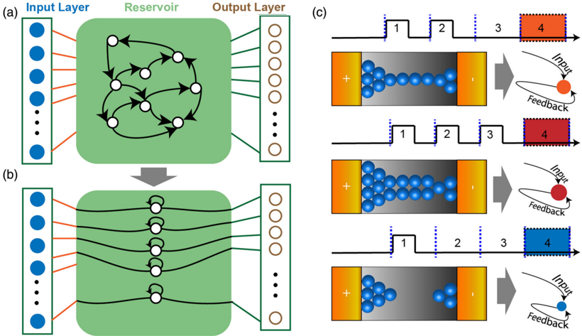
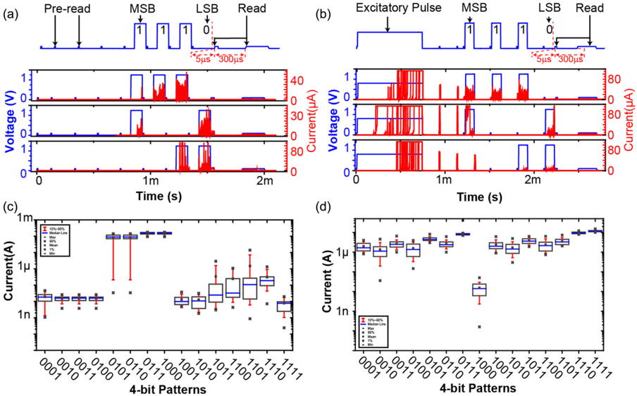
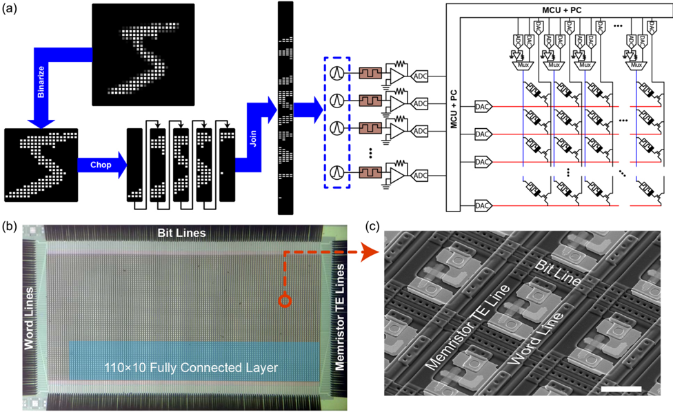
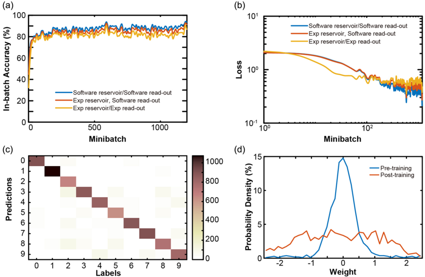
Reservoir computing (RC) is a framework that can extract features from a temporal input into a higher‐dimension feature space. The reservoir is followed by a readout layer that can analyze the extracted features to accomplish tasks such as inference and classification. RC systems inherently exhibit an advantage, since the training is only performed at the readout layer, and therefore they are able to compute complicated temporal data with a low training cost. Herein, a physical reservoir computing system using diffusive memristor‐based reservoir and drift memristor‐based readout layer is experimentally implemented. The rich nonlinear dynamic behavior exhibited by a diffusive memristor due to Ag migration and the robust in situ training of drift memristor arrays makes the combined system ideal for temporal pattern classification. It is then demonstrated experimentally that the RC system can successfully identify handwritten digits from the Modified National Institute of Standards and Technology (MNIST) dataset, achieving an accuracy of 83%.
Overview
The claims and statistics of this paper haven’t been checked yet.
Free: it reads the open-access text and checks the first 5 claims that cite a source we can check. Create a free account to check every claim.
Integrity signals
Registry
Cites
Statistics
Figures
Verification
Claims the paper makes
The claims and statistics of this paper haven’t been checked yet.
Free: it reads the open-access text and checks the first 5 claims that cite a source we can check. Create a free account to check every claim.
Self-check
Percentages, sums and reported differences re-computed from the paper’s own numbers.
The self-check needs the paper’s full text.
Citations
Cites
Deep learning in neural networks: an overview
Schmidhuber, J. (2015) · Neural Networks · doi:10.1016/j.neunet.2014.09.003 · Cited by 18,570
Strukov, D. B., Snider, G. S., Stewart, D. R., & Williams, R. S. (2008) · Nature · doi:10.1038/nature06932 · Cited by 11,828
Nanoscale Memristor Device as Synapse in Neuromorphic Systems
Jo, S. H., Chang, T., Ebong, I., Bhadviya, B. B., Mazumder, P., & Lu, W. (2010) · Nano Letters · doi:10.1021/nl904092h · Cited by 4,174
Maass, W., Natschläger, T., & Markram, H. (2002) · Neural Computation · doi:10.1162/089976602760407955 · Cited by 4,025
Memristive devices for computing
Yang, J. J., Strukov, D. B., & Stewart, D. R. (2013) · Nature Nanotechnology · doi:10.1038/nnano.2012.240 · Cited by 3,885
Self-citationHarnessing Nonlinearity: Predicting Chaotic Systems and Saving Energy in Wireless Communication
Jaeger, H., & Haas, H. (2004) · Science · doi:10.1126/science.1091277 · Cited by 3,811
Networks of spiking neurons: The third generation of neural network models
Maass, W. (1997) · Neural Networks · doi:10.1016/s0893-6080(97)00011-7 · Cited by 3,481
Training and operation of an integrated neuromorphic network based on metal-oxide memristors
Prezioso, M., Merrikh-Bayat, F., Hoskins, B. D., Adam, G. C., Likharev, K. K., & Strukov, D. B. (2015) · Nature · doi:10.1038/nature14441 · Cited by 3,001
Reservoir computing approaches to recurrent neural network training
Lukoševičius, M., & Jaeger, H. (2009) · Computer Science Review · doi:10.1016/j.cosrev.2009.03.005 · Cited by 2,956
Memristors with diffusive dynamics as synaptic emulators for neuromorphic computing
Wang, Z., Joshi, S., Savel’ev, S. E., Jiang, H., Midya, R., Lin, P., Hu, M., Ge, N., Strachan, J. P., Li, Z., et al. (2017) · Nature Materials · doi:10.1038/nmat4756 · Cited by 2,358
Self-citationShort-term plasticity and long-term potentiation mimicked in single inorganic synapses
Ohno, T., Hasegawa, T., Tsuruoka, T., Terabe, K., Gimzewski, J. K., & Aono, M. (2011) · Nature Materials · doi:10.1038/nmat3054 · Cited by 1,793
Neuromorphic computing with nanoscale spintronic oscillators
Torrejon, J., Riou, M., Araujo, F. A., Tsunegi, S., Khalsa, G., Querlioz, D., Bortolotti, P., Cros, V., Yakushiji, K., Fukushima, A., et al. (2017) · Nature · doi:10.1038/nature23011 · Cited by 1,374
Analogue signal and image processing with large memristor crossbars
Li, C., Hu, M., Li, Y., Jiang, H., Ge, N., Montgomery, E., Zhang, J., Song, W., Dávila, N., Graves, C. E., et al. (2017) · Nature Electronics · doi:10.1038/s41928-017-0002-z · Cited by 1,292
Self-citationObservation of conducting filament growth in nanoscale resistive memories
Yang, Y., Gao, P., Gaba, S., Chang, T., Pan, X., & Lu, W. (2012) · Nature Communications · doi:10.1038/ncomms1737 · Cited by 1,208
Stochastic phase-change neurons
Tuma, T., Pantazi, A., Le Gallo, M., Sebastian, A., & Eleftheriou, E. (2016) · Nature Nanotechnology · doi:10.1038/nnano.2016.70 · Cited by 1,109
Fully memristive neural networks for pattern classification with unsupervised learning
Wang, Z., Joshi, S., Savel’ev, S., Song, W., Midya, R., Li, Y., Rao, M., Yan, P., Asapu, S., Zhuo, Y., et al. (2018) · Nature Electronics · doi:10.1038/s41928-018-0023-2 · Cited by 1,106
Self-citationA scalable neuristor built with Mott memristors
Pickett, M. D., Medeiros-Ribeiro, G., & Williams, R. S. (2013) · Nature Materials · doi:10.1038/nmat3510 · Cited by 1,033
Reservoir computing using dynamic memristors for temporal information processing
Du, C., Cai, F., Zidan, M. A., Ma, W., Lee, S. H., & Lu, W. D. (2017) · Nature Communications · doi:10.1038/s41467-017-02337-y · Cited by 1,015
Nanoscience and Technology: A Collection of Reviews from Nature Journals
Rinaldi, G. (2010) · Assembly Automation · doi:10.1108/aa.2010.03330bae.001 · Cited by 1,012
Efficient and self-adaptive in-situ learning in multilayer memristor neural networks
Li, C., Belkin, D., Li, Y., Yan, P., Hu, M., Ge, N., Jiang, H., Montgomery, E., Lin, P., Wang, Z., et al. (2018) · Nature Communications · doi:10.1038/s41467-018-04484-2 · Cited by 931
Self-citationFace classification using electronic synapses
Yao, P., Wu, H., Gao, B., Eryilmaz, S. B., Huang, X., Zhang, W., Zhang, Q., Deng, N., Shi, L., Wong, H.-S. P., et al. (2017) · Nature Communications · doi:10.1038/ncomms15199 · Cited by 909
Recurrent Neural Networks for Prediction: Learning Algorithms, Architectures and Stability
Mandic, D. P., & Chambers, J. A. (2001) · Wiley eBooks · doi:10.1002/047084535x · Cited by 829
Optoelectronic Reservoir Computing
Paquot, Y., Duport, F., Smerieri, A., Dambre, J., Schrauwen, B., Haelterman, M., & Massar, S. (2012) · Scientific Reports · doi:10.1038/srep00287 · Cited by 783
Artificial neural networks in hardware: A survey of two decades of progress
Misra, J., & Saha, I. (2010) · Neurocomputing · doi:10.1016/j.neucom.2010.03.021 · Cited by 646
Pattern classification by memristive crossbar circuits using ex situ and in situ training
Alibart, F., Zamanidoost, E., & Strukov, D. B. (2013) · Nature Communications · doi:10.1038/ncomms3072 · Cited by 642
High switching endurance in TaOx memristive devices
Yang, J. J., Zhang, M.-X., Strachan, J. P., Miao, F., Pickett, M. D., Kelley, R. D., Medeiros-Ribeiro, G., & Williams, R. S. (2010) · Applied Physics Letters · doi:10.1063/1.3524521 · Cited by 637
Self-citationSparse coding with memristor networks
Sheridan, P. M., Cai, F., Du, C., Ma, W., Zhang, Z., & Lu, W. D. (2017) · Nature Nanotechnology · doi:10.1038/nnano.2017.83 · Cited by 619
Long short-term memory networks in memristor crossbar arrays
Li, C., Wang, Z., Rao, M., Belkin, D., Song, W., Jiang, H., Yan, P., Li, Y., Lin, P., Hu, M., et al. (2019) · Nature Machine Intelligence · doi:10.1038/s42256-018-0001-4 · Cited by 429
Self-citationFinding a roadmap to achieve large neuromorphic hardware systems
Hasler, J., & Marr, B. (2013) · Frontiers in Neuroscience · doi:10.3389/fnins.2013.00118 · Cited by 392
Anatomy of Ag/Hafnia‐Based Selectors with 1010 Nonlinearity
Midya, R., Wang, Z., Zhang, J., Savel'ev, S. E., Li, C., Rao, M., Jang, M. H., Joshi, S., Jiang, H., Lin, P., et al. (2017) · Advanced Materials · doi:10.1002/adma.201604457 · Cited by 379
Self-citationReinforcement learning with analogue memristor arrays
Wang, Z., Li, C., Song, W., Rao, M., Belkin, D., Li, Y., Yan, P., Jiang, H., Lin, P., Hu, M., et al. (2019) · Nature Electronics · doi:10.1038/s41928-019-0221-6 · Cited by 370
Self-citationSerb, A., Bill, J., Khiat, A., Berdan, R., Legenstein, R., & Prodromakis, T. (2016) · Nature Communications · doi:10.1038/ncomms12611 · Cited by 339
Surface diffusion-limited lifetime of silver and copper nanofilaments in resistive switching devices
Wang, W., Wang, M., Ambrosi, E., Bricalli, A., Laudato, M., Sun, Z., Chen, X., & Ielmini, D. (2019) · Nature Communications · doi:10.1038/s41467-018-07979-0 · Cited by 328
Neural Networks for Applied Sciences and Engineering
Samarasinghe, S. (2016) · Auerbach Publications eBooks · doi:10.1201/9780849333750 · Cited by 307
Bio-Inspired Stochastic Computing Using Binary CBRAM Synapses
Suri, M., Querlioz, D., Bichler, O., Palma, G., Vianello, E., Vuillaume, D., Gamrat, C., & DeSalvo, B. (2013) · IEEE Transactions on Electron Devices · doi:10.1109/ted.2013.2263000 · Cited by 229
Analog Memristive Synapse in Spiking Networks Implementing Unsupervised Learning
Covi, E., Brivio, S., Serb, A., Prodromakis, T., Fanciulli, M., & Spiga, S. (2016) · Frontiers in Neuroscience · doi:10.3389/fnins.2016.00482 · Cited by 181
Jaiswal, A., Roy, S., Srinivasan, G., & Roy, K. (2017) · IEEE Transactions on Electron Devices · doi:10.1109/ted.2017.2671353 · Cited by 91
Research works printed but not linked: 5
- Jaeger H., 2001, German National Research Center for Information Technology GMD Technical Report, 13
- J. J.Steil in2004 IEEE Int. Joint Conf. on Neural Networks (IEEE Cat. No.04CH37541) Vol.842 IEEE Budapest2004 pp.843–848.
- Jaeger H., 2002, Tutorial on Training Recurrent Neural Networks, Covering BPPT, RTRL, EKF and the “Echo State Network” Approach
- J.Lin Annadi S.Sonde C.Chen L.Stan K. V. L. V.Achari S.Ramanathan S.Guha in2016 IEEE Int. Electron Devices Meeting (IEDM) IEEE San Francisco2016 pp.34.35.31–34.35.34.
- 10.1038/s41928-019-0221-6 · DOI · Paper page
Cited by
Resistive switching materials for information processing
Wang, Z., Wu, H., Burr, G. W., Hwang, C. S., Wang, K. L., Xia, Q., & Yang, J. J. (2020) · Nature Reviews Materials · doi:10.1038/s41578-019-0159-3 · Cited by 1,214
Self-citationTang, J., Yuan, F., Shen, X., Wang, Z., Rao, M., He, Y., Sun, Y., Li, X., Zhang, W., Li, Y., et al. (2019) · Advanced Materials · doi:10.1002/adma.201902761 · Cited by 834
Self-citationDynamic memristor-based reservoir computing for high-efficiency temporal signal processing
(2021) · doi:10.1038/s41467-020-20692-1 · Cited by 597
Physical reservoir computing—an introductory perspective
Nakajima, K. (2020) · Japanese Journal of Applied Physics · doi:10.35848/1347-4065/ab8d4f · Cited by 422
Milano, G., Pedretti, G., Montano, K., Ricci, S., Hashemkhani, S., Boarino, L., Ielmini, D., & Ricciardi, C. (2022) · Nature Materials · doi:10.1038/s41563-021-01099-9 · Cited by 462
Metadata
- Authors
- Midya, R., Wang, Z., Asapu, S., Zhang, X., Rao, M., Song, W., Zhuo, Y., Upadhyay, N., Xia, Q., & Yang, J. J.
- Affiliations
- University of Massachusetts Amherst (US)
- Corresponding author
- Xia, Qiangfei
- Yang, J. Joshua
- ORCID
- Venue
- Advanced Intelligent Systems
- Publisher
- Wiley
- Published
- 2019-09-25
- Volume
- 1
- Issue
- 7
- ISSN
- 2640-4567 (ISSN-L)
- OpenAlex
- W2971405544
- Cited by
- 279
- References
- 38
- Citations by year
- 2026: 36 · 2025: 49 · 2024: 59 · 2023: 55 · 2022: 36 · 2021: 26 · 2020: 15 · 2019: 2
- FWCI
- 9.01
- Type
- journal article
- Language
- en
- Open access
- gold
- doi.org
- Locations
- Advanced Intelligent Systems (publishedVersion, cc-by)
- Funders
- Air Force Office of Scientific Research (FA9550-19-1-0213)
- Topics
- Physical Sciences › Computer Science › Artificial Intelligence › Neural Networks and Reservoir Computing
- Physical Sciences › Engineering › Electrical and Electronic Engineering › Advanced Memory and Neural Computing
- Physical Sciences › Mathematics › Theoretical Computer Science › DNA and Biological Computing
- Keywords
- reservoir computing, diffusive memristors, physical reservoir computing, nonlinear dynamics, in situ training, handwritten digit recognition, MNIST
About these checks
Registry, retraction, Cites and statistics results are computed, not judged, with one exception: a printed reference that no index lists is read once by a model before it counts as a citation error. Claims are extracted by a model and kept only when their quote appears verbatim in the text; each cited source is then checked, with a model’s help, for whether it says what the claim relies on. Those verdicts can be wrong — read the claim’s quote and the cited source before relying on one.
Statistics and arithmetic are recomputed, not judged.
Confidence bands are shown only for fields calibrated on our annotated test set. None is calibrated yet, so no band is shown.
What counts as a claim ›How we measure confidence ›How we check this ›
Are you an author, or do you see a problem with this page? Request a review
Data sources
Bibliographic data: Semantic Scholar, OpenAlex, Crossref.
Contains information from the Semantic Scholar Academic Graph Datasets, made available under the ODC Attribution License (ODC-BY 1.0).
Semantic Scholar’s data is described in: Kinney, R., et al. (2023). The Semantic Scholar Open Data Platform. arXiv:2301.10140.
