

Ultrathin metal-organic framework array for efficient electrocatalytic water splitting
Open accessThe DOI matches its Crossref record; 30 of the 30 references it cites were found in a registry or an index.
Abstract
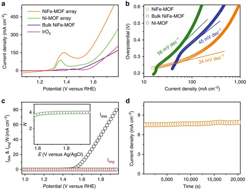
Two-dimensional metal-organic frameworks represent a family of materials with attractive chemical and structural properties, which are usually prepared in the form of bulk powders. Here we show a generic approach to fabricate ultrathin nanosheet array of metal-organic frameworks on different substrates through a dissolution–crystallization mechanism. These materials exhibit intriguing properties for electrocatalysis including highly exposed active molecular metal sites owning to ultra-small thickness of nanosheets, improved electrical conductivity and a combination of hierarchical porosity. We fabricate a nickel-iron-based metal-organic framework array, which demonstrates superior electrocatalytic performance towards oxygen evolution reaction with a small overpotential of 240 mV at 10 mA cm −2 , and robust operation for 20,000 s with no detectable activity decay. Remarkably, the turnover frequency of the electrode is 3.8 s −1 at an overpotential of 400 mV. We further demonstrate the promise of these electrodes for other important catalytic reactions including hydrogen evolution reaction and overall water splitting.
Overview
The claims and statistics of this paper haven’t been checked yet.
Free: it reads the open-access text and checks the first 5 claims that cite a source we can check. Create a free account to check every claim.
Integrity signals
Registry
Cites
Statistics
Figures



Verification
Claims the paper makes
The claims and statistics of this paper haven’t been checked yet.
Free: it reads the open-access text and checks the first 5 claims that cite a source we can check. Create a free account to check every claim.
Self-check
Percentages, sums and reported differences re-computed from the paper’s own numbers.
The self-check needs the paper’s full text.
Citations
Cites
Trotochaud, L., Young, S. L., Ranney, J. K., & Boettcher, S. W. (2014) · Journal of the American Chemical Society · doi:10.1021/ja502379c · Cited by 3,588
Enhanced catalytic activity in strained chemically exfoliated WS2 nanosheets for hydrogen evolution
Voiry, D., Yamaguchi, H., Li, J., Silva, R., Alves, D. C. B., Fujita, T., Chen, M., Asefa, T., Shenoy, V. B., Eda, G., et al. (2013) · Nature Materials · doi:10.1038/nmat3700 · Cited by 2,641
Water photolysis at 12.3% efficiency via perovskite photovoltaics and Earth-abundant catalysts
Luo, J., Im, J.-H., Mayer, M. T., Schreier, M., Nazeeruddin, M. K., Park, N.-G., Tilley, S. D., Fan, H. J., & Grätzel, M. (2014) · Science · doi:10.1126/science.1258307 · Cited by 2,509
Conductive MOF electrodes for stable supercapacitors with high areal capacitance
Sheberla, D., Bachman, J. C., Elias, J. S., Sun, C.-J., Shao-Horn, Y., & Dincă, M. (2017) · Nature Materials · doi:10.1038/nmat4766 · Cited by 2,370
Stable single-unit-cell nanosheets of zeolite MFI as active and long-lived catalysts
Choi, M., Na, K., Kim, J., Sakamoto, Y., Terasaki, O., & Ryoo, R. (2009) · Nature · doi:10.1038/nature08288 · Cited by 2,237
Ultrathin Two-Dimensional Nanomaterials
Zhang, H. (2015) · ACS Nano · doi:10.1021/acsnano.5b05040 · Cited by 2,167
Oxygen vacancies enhance pseudocapacitive charge storage properties of MoO3−x
Kim, H.-S., Cook, J. B., Lin, H., Ko, J. S., Tolbert, S. H., Ozolins, V., & Dunn, B. (2017) · Nature Materials · doi:10.1038/nmat4810 · Cited by 2,166
Lu, X., & Zhao, C. (2015) · Nature Communications · doi:10.1038/ncomms7616 · Cited by 1,995
Self-citationElectrically Conductive Porous Metal–Organic Frameworks
Sun, L., Campbell, M. G., & Dincă, M. (2016) · Angewandte Chemie International Edition · doi:10.1002/anie.201506219 · Cited by 1,901
Ma, T. Y., Dai, S., Jaroniec, M., & Qiao, S. Z. (2014) · Journal of the American Chemical Society · doi:10.1021/ja5082553 · Cited by 1,846
Jin, H., Wang, J., Su, D., Wei, Z., Pang, Z., & Wang, Y. (2015) · Journal of the American Chemical Society · doi:10.1021/ja5127165 · Cited by 1,765
Metal-organic framework nanosheets as building blocks for molecular sieving membranes
Peng, Y., Li, Y., Ban, Y., Jin, H., Jiao, W., Liu, X., & Yang, W. (2014) · Science · doi:10.1126/science.1254227 · Cited by 1,731
Nanoscale nickel oxide/nickel heterostructures for active hydrogen evolution electrocatalysis
Gong, M., Zhou, W., Tsai, M.-C., Zhou, J., Guan, M., Lin, M.-C., Zhang, B., Hu, Y., Wang, D.-Y., Yang, J., et al. (2014) · Nature Communications · doi:10.1038/ncomms5695 · Cited by 1,701
Kruk, M., Jaroniec, M., & Sayari, A. (1997) · Langmuir · doi:10.1021/la970776m · Cited by 1,428
Applications of water stable metal–organic frameworks
Wang, C., Liu, X., Keser Demir, N., Chen, J. P., & Li, K. (2016) · Chemical Society Reviews · doi:10.1039/c6cs00362a · Cited by 1,249
Ultrathin 2D Metal–Organic Framework Nanosheets
Zhao, M., Wang, Y., Ma, Q., Huang, Y., Zhang, X., Ping, J., Zhang, Z., Lu, Q., Yu, Y., Xu, H., et al. (2015) · Advanced Materials · doi:10.1002/adma.201503648 · Cited by 1,190
Wang, L., Feng, X., Ren, L., Piao, Q., Zhong, J., Wang, Y., Li, H., Chen, Y., & Wang, B. (2015) · Journal of the American Chemical Society · doi:10.1021/jacs.5b01613 · Cited by 1,025
Jahan, M., Liu, Z., & Loh, K. P. (2013) · Advanced Functional Materials · doi:10.1002/adfm.201300510 · Cited by 1,016
Zhong, H., Wang, J., Zhang, Y., Xu, W., Xing, W., Xu, D., Zhang, Y., & Zhang, X. (2014) · Angewandte Chemie International Edition · doi:10.1002/anie.201408990 · Cited by 938
NixCo3−xO4 Nanowire Arrays for Electrocatalytic Oxygen Evolution
Li, Y., Hasin, P., & Wu, Y. (2010) · Advanced Materials · doi:10.1002/adma.200903896 · Cited by 894
Jiang, N., You, B., Sheng, M., & Sun, Y. (2015) · Angewandte Chemie International Edition · doi:10.1002/anie.201501616 · Cited by 844
Electrochemical oxygen reduction catalysed by Ni3(hexaiminotriphenylene)2
Miner, E. M., Fukushima, T., Sheberla, D., Sun, L., Surendranath, Y., & Dincă, M. (2016) · Nature Communications · doi:10.1038/ncomms10942 · Cited by 710
Chen, S., Duan, J., Jaroniec, M., & Qiao, S. Z. (2013) · Angewandte Chemie International Edition · doi:10.1002/anie.201306166 · Cited by 595
Self-citationPorous Field-Effect Transistors Based on a Semiconductive Metal–Organic Framework
Wu, G., Huang, J., Zang, Y., He, J., & Xu, G. (2017) · Journal of the American Chemical Society · doi:10.1021/jacs.6b08511 · Cited by 490
Portehault, D., Cassaignon, S., Baudrin, E., & Jolivet, J.-P. (2007) · Chemistry of Materials · doi:10.1021/cm071654a · Cited by 188
Ren, L., Guo, Q., Kumar, P., Orazov, M., Xu, D., Alhassan, S. M., Mkhoyan, K. A., Davis, M. E., & Tsapatsis, M. (2015) · Angewandte Chemie International Edition · doi:10.1002/anie.201505334 · Cited by 170
Lee, S., Nam, G., Sun, J., Lee, J., Lee, H., Chen, W., Cho, J., & Cui, Y. (2016) · Angewandte Chemie International Edition · doi:10.1002/anie.201602851 · Cited by 141
Gong, Y., Shi, H., Jiang, P.-G., Hua, W., & Lin, J. (2013) · Crystal Growth & Design · doi:10.1021/cg401529u · Cited by 63
Homonuclear Mixed‐Valent Cobalt Imidazolate Framework for Oxygen‐Evolution Electrocatalysis
Flügel, E. A., Lau, V. W., Schlomberg, H., Glaum, R., & Lotsch, B. V. (2015) · Chemistry - A European Journal · doi:10.1002/chem.201504151 · Cited by 50
Kaduk, J. A., & Hanko, J. A. (2001) · Journal of Applied Crystallography · doi:10.1107/s0021889801012857 · Cited by 25
Cited by
A review on fundamentals for designing oxygen evolution electrocatalysts
Song, J., Wei, C., Huang, Z.-F., Liu, C., Zeng, L., Wang, X., & Xu, Z. J. (2020) · Chemical Society Reviews · doi:10.1039/c9cs00607a · Cited by 2,936
Emerging Two-Dimensional Nanomaterials for Electrocatalysis
Jin, H., Guo, C., Liu, X., Liu, J., Vasileff, A., Jiao, Y., Zheng, Y., & Qiao, S.-Z. (2018) · Chemical Reviews · doi:10.1021/acs.chemrev.7b00689 · Cited by 2,029
Electrically Conductive Metal–Organic Frameworks
Xie, L. S., Skorupskii, G., & Dincă, M. (2020) · Chemical Reviews · doi:10.1021/acs.chemrev.9b00766 · Cited by 1,999
Bavykina, A., Kolobov, N., Khan, I. S., Bau, J. A., Ramirez, A., & Gascon, J. (2020) · Chemical Reviews · doi:10.1021/acs.chemrev.9b00685 · Cited by 1,754
Mahmood, N., Yao, Y., Zhang, J., Pan, L., Zhang, X., & Zou, J. (2018) · Advanced Science · doi:10.1002/advs.201700464 · Cited by 1,676
Metadata
- Authors
- Duan, J., Chen, S., & Zhao, C.
- Affiliations
- UNSW Sydney (AU)
- Corresponding author
- Zhao, Chuan
- Venue
- Nature Communications
- Published
- 2017-06-05
- Volume
- 8
- Issue
- 1
- Pages
- 15341-15341
- ISSN
- 2041-1723 (ISSN-L)
- PMC
- PMC5465318
- OpenAlex
- W2621868363
- Cited by
- 1,319
- References
- 30
- Citations by year
- 2026: 57 · 2025: 102 · 2024: 130 · 2023: 140 · 2022: 135 · 2021: 206 · 2020: 240 · 2019: 173 · 2018: 123 · 2017: 13
- FWCI
- 40.14
- Type
- journal article
- Language
- en
- Open access
- gold
- doi.org
- Licence
- cc-by
- creativecommons.org/licenses/by/4.0 (tdm)
- creativecommons.org/licenses/by/4.0 (vor)
- Locations
- Nature Communications (publishedVersion, cc-by)
- Europe PMC (PubMed Central) (publishedVersion, cc-by)
- PubMed Central (publishedVersion, cc-by)
- PubMed (publishedVersion)
- RePEc: Research Papers in Economics (submittedVersion)
- DOAJ (DOAJ: Directory of Open Access Journals) (submittedVersion, cc-by-sa)
- Funders
- University of New South Wales
- Australian Research Council (DP160103107)
- Topics
- Physical Sciences › Energy › Renewable Energy, Sustainability and the Environment › Electrocatalysts for Energy Conversion
- Physical Sciences › Chemistry › Inorganic Chemistry › Metal-Organic Frameworks: Synthesis and Applications
- Physical Sciences › Energy › Renewable Energy, Sustainability and the Environment › CO2 Reduction Techniques and Catalysts
- Keywords
- metal-organic frameworks, ultrathin nanosheets, nanosheet arrays, dissolution-crystallization, oxygen evolution reaction, hydrogen evolution reaction, overall water splitting, electrocatalysis, hierarchical porosity, electrical conductivity, turnover frequency
About these checks
Registry, retraction, Cites and statistics results are computed, not judged, with one exception: a printed reference that no index lists is read once by a model before it counts as a citation error. Claims are extracted by a model and kept only when their quote appears verbatim in the text; each cited source is then checked, with a model’s help, for whether it says what the claim relies on. Those verdicts can be wrong — read the claim’s quote and the cited source before relying on one.
Statistics and arithmetic are recomputed, not judged.
Confidence bands are shown only for fields calibrated on our annotated test set. None is calibrated yet, so no band is shown.
What counts as a claim ›How we measure confidence ›How we check this ›
Are you an author, or do you see a problem with this page? Request a review
Data sources
Bibliographic data: Semantic Scholar, OpenAlex, Crossref.
Contains information from the Semantic Scholar Academic Graph Datasets, made available under the ODC Attribution License (ODC-BY 1.0).
Semantic Scholar’s data is described in: Kinney, R., et al. (2023). The Semantic Scholar Open Data Platform. arXiv:2301.10140.
