

The DOI matches its Crossref record; 49 of the 49 references it cites were found in a registry or an index.
A handheld bioprinter for multi-material printing of complex constructs
Open accessAbstract
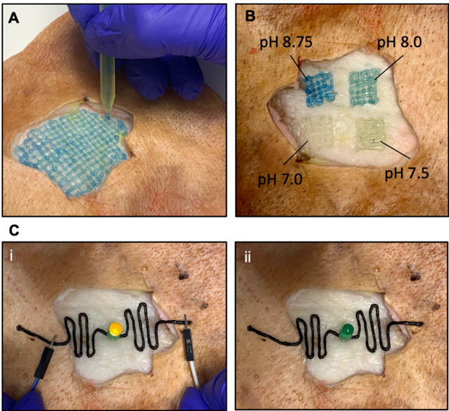
In situ bioprinting—the process of depositing bioinks at a defected area, has recently emerged as a versatile technology for tissue repair and restoration via site-specific delivery of pro-healing constructs. The ability to print multiple materials in situ is an exciting approach that allows simultaneous or sequential dispensing of different materials and cells to achieve tissue biomimicry. Herein, we report a modular handheld bioprinter that deposits a variety of bioinks in situ with exquisite control over their physical and chemical properties. Combined stereolithography 3D printing and microfluidic technologies allowed us to develop a novel low-priced handheld bioprinter. The ergonomic design of the handheld bioprinter facilitate the shape-controlled biofabrication of multi-component fibers with different cross-sectional shapes and material compositions. Furthermore, the capabilities of the produced fibers in the local delivery of therapeutic agents was demonstrated by incorporating drug-loaded microcarriers, extending the application of the printed fibers to on-demand, temporal, and dosage-control drug delivery platforms. Also, the versatility of this platform to produce biosensors and wearable electronics was demonstrated via incorporating conductive materials and integrating pH-responsive dyes. The handheld printer’s efficacy in generating cell-laden fibers with high cell viability for site-specific cell delivery was shown by producing single-component and multi-component cell-laden fibers. In particular, the multi-component fibers were able to model the invasion of cancer cells into the adjacent tissue.
Overview
The claims and statistics of this paper haven’t been checked yet.
Free: it reads the open-access text and checks the first 5 claims that cite a source we can check. Create a free account to check every claim.
Integrity signals
Registry
Cites
Statistics
Figures


Verification
Claims the paper makes
The claims and statistics of this paper haven’t been checked yet.
Free: it reads the open-access text and checks the first 5 claims that cite a source we can check. Create a free account to check every claim.
Claims other papers make about this one
Each is checked against this paper’s own text: does it say what the citing paper says it does?
The cited source says what the claim attributes to it.
In the citing paper
“Handheld 3D bioprinters offer a potential solution for implementing in situ 3D bioprinting technology in tissue repair approaches [11–13].”
From Development of silk microfiber-reinforced bioink for muscle tissue engineering and in situ printing by a handheld 3D printer (2025) · cites this paper as [11]
The cited source says what the claim attributes to it.
In the citing paper
“Different materials and cell types can be printed making it well-suited to address multicellular complexity in tissue repair and regeneration [11, 12, 14, 15].”
From Development of silk microfiber-reinforced bioink for muscle tissue engineering and in situ printing by a handheld 3D printer (2025) · cites this paper as [11]
Self-check
Percentages, sums and reported differences re-computed from the paper’s own numbers.
The self-check needs the paper’s full text.
Citations
Cites
U1 snRNP regulates cancer cell migration and invasion in vitro
Oh, J.-M., Venters, C. C., Di, C., Pinto, A. M., Wan, L., Younis, I., Cai, Z., Arai, C., So, B. R., Duan, J., et al. (2020) · Nature Communications · doi:10.1038/s41467-019-13993-7 · Cited by 7,157
3D bioprinting of tissues and organs
Murphy, S. V., & Atala, A. (2014) · Nature Biotechnology · doi:10.1038/nbt.2958 · Cited by 7,034
3D bioprinting of collagen to rebuild components of the human heart
Lee, A., Hudson, A. R., Shiwarski, D. J., Tashman, J. W., Hinton, T. J., Yerneni, S., Bliley, J. M., Campbell, P. G., & Feinberg, A. W. (2019) · Science · doi:10.1126/science.aav9051 · Cited by 1,782
Multivascular networks and functional intravascular topologies within biocompatible hydrogels
Grigoryan, B., Paulsen, S. J., Corbett, D. C., Sazer, D. W., Fortin, C. L., Zaita, A. J., Greenfield, P. T., Calafat, N. J., Gounley, J. P., Ta, A. H., et al. (2019) · Science · doi:10.1126/science.aav9750 · Cited by 1,396
Progress in 3D bioprinting technology for tissue/organ regenerative engineering
Matai, I., Kaur, G., Seyedsalehi, A., McClinton, A., & Laurencin, C. T. (2020) · Biomaterials · doi:10.1016/j.biomaterials.2019.119536 · Cited by 1,156
Vascularization is the key challenge in tissue engineering
Novosel, E. C., Kleinhans, C., & Kluger, P. J. (2011) · Advanced Drug Delivery Reviews · doi:10.1016/j.addr.2011.03.004 · Cited by 1,062
A Review of 3D Printing Technology for Medical Applications
Yan, Q., Dong, H., Su, J., Han, J., Song, B., Wei, Q., & Shi, Y. (2018) · Engineering · doi:10.1016/j.eng.2018.07.021 · Cited by 720
Han, L., Lu, X., Wang, M., Gan, D., Deng, W., Wang, K., Fang, L., Liu, K., Chan, C. W., Tang, Y., et al. (2017) · Small · doi:10.1002/smll.201601916 · Cited by 699
Direct Human Cartilage Repair Using Three-Dimensional Bioprinting Technology
Cui, X., Breitenkamp, K., Finn, M. G., Lotz, M., & D'Lima, D. D. (2012) · Tissue Engineering Part A · doi:10.1089/ten.tea.2011.0543 · Cited by 686
Photopolymerizable Biomaterials and Light-Based 3D Printing Strategies for Biomedical Applications
Yu, C., Schimelman, J., Wang, P., Miller, K. L., Ma, X., You, S., Guan, J., Sun, B., Zhu, W., & Chen, S. (2020) · Chemical Reviews · doi:10.1021/acs.chemrev.9b00810 · Cited by 579
Cited by
Hydrogel Fibers‐Based Biointerfacing
Chen, X., Feng, Y., Zhang, P., Ni, Z., Xue, Y., & Liu, J. (2024) · Advanced Materials · doi:10.1002/adma.202413476 · Cited by 109
Jafari, A., Niknezhad, S. V., Kaviani, M., Saleh, W. F., Wong, N., Vliet, P. P. V., Moraes, C., Ajji, A., Kadem, L., Azarpira, N., et al. (2023) · Advanced Functional Materials · doi:10.1002/adfm.202305188 · Cited by 76
Self-citation3D Bioprinting for Vascularization
Mir, A., Lee, E., Shih, W., Koljaka, S., Wang, A., Jorgensen, C., Hurr, R., Dave, A., Sudheendra, K., & Hibino, N. (2023) · Bioengineering · doi:10.3390/bioengineering10050606 · Cited by 74
Eslahi, N., Soleimani, F., Lotfi, R., Mohandes, F., Simchi, A., & Razavi, M. (2024) · Progress in Materials Science · doi:10.1016/j.pmatsci.2024.101293 · Cited by 48
In Situ Bioprinting: Process, Bioinks, and Applications
Jain, P., Kathuria, H., Ramakrishna, S., Parab, S., Pandey, M. M., & Dubey, N. (2024) · ACS Applied Bio Materials · doi:10.1021/acsabm.3c01303 · Cited by 54
Metadata
- Authors
- Pagan, E., Stefanek, E., Seyfoori, A., Razzaghi, M., Chehri, B., Mousavi, A., Arnaldi, P., Ajji, Z., Dartora, D. R., Dabiri, S. M. H., Nuyt, A. M., Khademhosseini, A., Savoji, H., & Akbari, M.
- Affiliations
- University of Victoria (CA)
- Centre Hospitalier Universitaire Sainte-Justine (CA)
- Terasaki Foundation (US)
- University of British Columbia (CA)
- Corresponding author
- Akbari, Mohsen
- ORCID
- Venue
- Biofabrication
- Publisher
- IOP Publishing
- Published
- 2023-05-02
- Volume
- 15
- Issue
- 3
- Pages
- 035012
- ISSN
- 1758-5082 (ISSN-L)
- 1758-5090
- OpenAlex
- W4324131326
- Cited by
- 43
- References
- 49
- Citations by year
- 2026: 11 · 2025: 15 · 2024: 14 · 2023: 3
- FWCI
- 3.40
- Type
- journal article
- Language
- en
- Open access
- hybrid
- doi.org
- Licence
- cc-by
- creativecommons.org/licenses/by/4.0 (vor)
- iopscience.iop.org/info/page/text-and-data-mining (tdm)
- Locations
- Biofabrication (publishedVersion, cc-by)
- PubMed (publishedVersion)
- UVic’s Research and Learning Repository (University of Victoria) (submittedVersion)
- PolyPublie (École Polytechnique de Montréal) (submittedVersion)
- Funders
- Canadian Foundation for Innovation
- Terasaki Institute for Biomedical Innovation
- Natural Sciences and Engineering Research Council of Canada
- Canadian Institutes for Health research
- Topics
- Physical Sciences › Engineering › Biomedical Engineering › 3D Printing in Biomedical Research
- Physical Sciences › Materials Science › Biomaterials › Electrospun Nanofibers in Biomedical Applications
- Health Sciences › Medicine › Surgery › Tissue Engineering and Regenerative Medicine
- Keywords
- in situ bioprinting, stereolithography 3D printing, on-demand drug delivery, biosensors, wearable electronics, pH-responsive dyes, tissue repair
- MeSH terms
- Cell Survival, Hydrogels, Tissue Engineering, Microfluidics, Tissue Scaffolds, Bioprinting, Printing, Three-Dimensional
About these checks
Registry, retraction, Cites and statistics results are computed, not judged, with one exception: a printed reference that no index lists is read once by a model before it counts as a citation error. Claims are extracted by a model and kept only when their quote appears verbatim in the text; each cited source is then checked, with a model’s help, for whether it says what the claim relies on. Those verdicts can be wrong — read the claim’s quote and the cited source before relying on one.
Statistics and arithmetic are recomputed, not judged.
Confidence bands are shown only for fields calibrated on our annotated test set. None is calibrated yet, so no band is shown.
What counts as a claim ›How we measure confidence ›How we check this ›
Are you an author, or do you see a problem with this page? Request a review
How to cite
Cite CoChat for the checks on this page, and the paper for its own findings.
- This page
- CoChat. (2026). Citation check: A handheld bioprinter for multi-material printing of complex constructs. https://app.cochat.ai/papers/10.1088/1758-5090/acc42c
- The paper
- Pagan, E., Stefanek, E., Seyfoori, A., Razzaghi, M., Chehri, B., Mousavi, A., Arnaldi, P., Ajji, Z., Dartora, D. R., Dabiri, S. M. H., Nuyt, A. M., Khademhosseini, A., Savoji, H., & Akbari, M. (2023). A handheld bioprinter for multi-material printing of complex constructs. Biofabrication. https://doi.org/10.1088/1758-5090/acc42c
Data sources
Bibliographic data: Semantic Scholar, OpenAlex, Crossref.
Contains information from the Semantic Scholar Academic Graph Datasets, made available under the ODC Attribution License (ODC-BY 1.0).
Semantic Scholar’s data is described in: Kinney, R., et al. (2023). The Semantic Scholar Open Data Platform. arXiv:2301.10140.
