

The DOI matches its Crossref record; 120 of the 121 references it cites were found in a registry or an index; none of the 79 sources its claims cite is checked for support yet.
Parallel Connection of Silicon Carbide MOSFETs—Challenges, Mechanism, and Solutions
Open accessAbstract
Power semiconductor devices are often connected in parallel to increase the current rating of the power conversion systems. However, due to mismatched circuit parameters or semiconductor fabrication discrepancies, the current of paralleled power semiconductor devices can be unbalanced, which potentially leads to accelerated aging and long-term reliability issues. The fast-switching speed of silicon carbide (SiC) devices aggravates this problem due to its higher sensitivity to parasitic parameters. Numerous efforts have been dedicated to analyzing and addressing the current imbalance issue of paralleling SiC devices. This article comprehensively summarizes and presents state-of-the-art research regarding the current imbalance in paralleled SiC devices. Degree of imbalance is proposed to comprehensively quantify the current mismatch. Starting with mechanism analysis, different types of current imbalance are categorized. Various device parameters and the package layout that impact the current distribution are investigated. The existing solutions including passive methods and active methods are concluded and categorized. This work also incorporates insight into the future development needs of high-power multichip SiC module packaging and driving technologies.
Overview
CoChat Summary
TL;DR
This review synthesizes the mechanisms and mitigation of current imbalance in paralleled SiC MOSFETs, proposing static and dynamic Degree of Imbalance (DoI) metrics. It categorizes causes into device parameters, circuit parasitics, and status indicators, and reviews passive and active current-sharing solutions.
Key findings
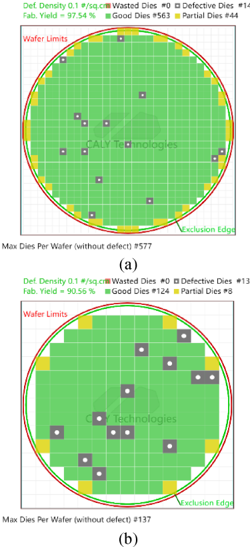
- Paralleling SiC MOSFETs is more challenging than paralleling Si IGBTs due to smaller dies, larger parameter spread, and faster switching. On a 6-inch wafer, yield falls from 97.54% for 5 × 5 mm dies to 90.56% for 10 × 10 mm dies; for ≤750 V, a single SiC die is about 100 A at 5 × 5 mm² versus about 300 A at 10 × 12 mm² for Si IGBT.
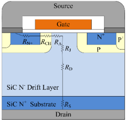
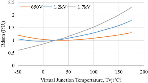
- Static imbalance is mainly from \(R_{dson}\) mismatch, while dynamic imbalance arises from \(V_{th}\), \(L_s\), gate delay, and related factors. \(R_{dson}\)’s positive temperature coefficient self-balances static current, but \(V_{th}\)’s negative temperature coefficient can self-aggravate and risk thermal runaway. For 650 V SiC, \(R_{CH}\) can exceed 50% of total \(R_{dson}\); for 1.7 kV, it can be below 30%.
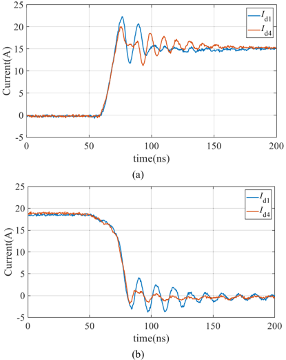
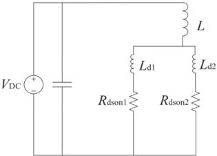
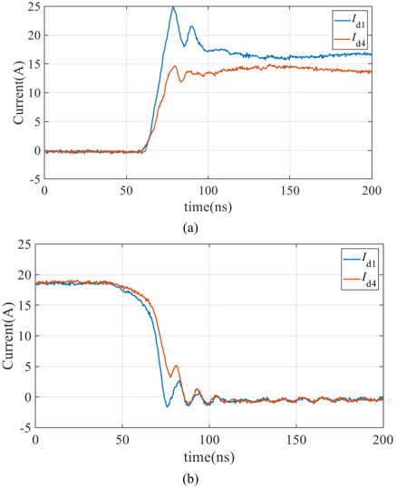
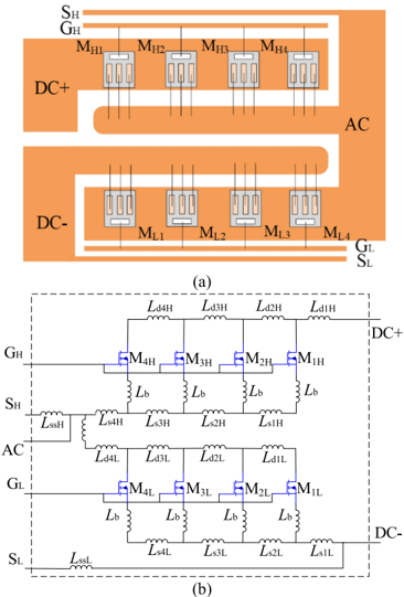
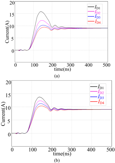
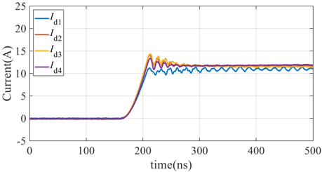
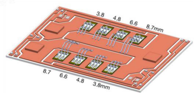
- \(L_s\) mismatch strongly affects dynamic current sharing; \(L_d\) has little dynamic impact but affects ringing and can affect static sharing if current changes; \(L_g\) mismatch is minor. An auxiliary source connection reduced peak current difference from 18 A to 9 A in a four-die module.
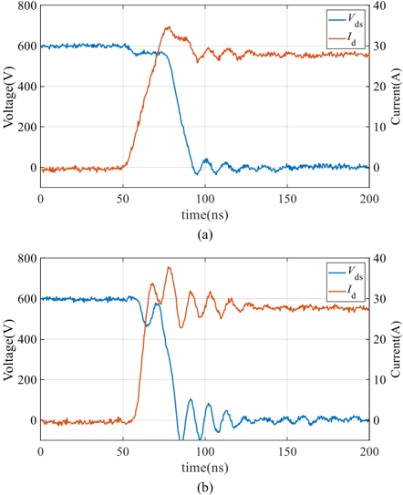
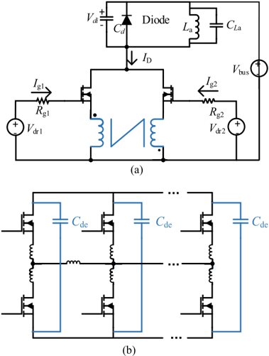
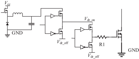
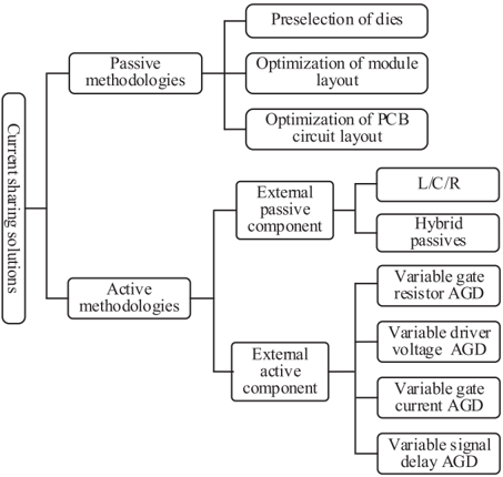
- Solutions are passive (die preselection/screening, symmetric layout) and active (external passive components, active gate drivers). Design rules are to reduce mismatched \(L_s\) and the \(di/dt\) applied across it. AGD is challenging because SiC transients can be within 100 ns, with \(di/dt\) up to 5 A/ns and \(dV/dt\) over 50 V/ns.
Methods
- Review/synthesis of state-of-the-art research on paralleling SiC MOSFETs; proposes static and dynamic DoI indices and categorizes pertinent parameters into device, circuit, and status types.
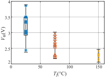
- Draws on cited experimental and simulation evidence, including curve-tracer testing of 20 SiC MOSFETs for \(V_{th}\), LTspice simulation for \(L_g\), PFC converter simulation for \(T_j\), and module current-sharing experiments.
Limitations
- The paper does not state limitations of the review itself.
- Evident from the text: as a review, it synthesizes prior work rather than providing a systematic meta-analysis or unified experimental validation across all methods.
- The paper notes technology limitations: AGD is premature for SiC due to very short switching transients (often within 100 ns; \(di/dt\) up to 5 A/ns), external passive components add cost and parasitics, and high-temperature known-good-die (KGD) for mass production remains challenging.
Model-written summary. Check it against the paper before relying on it.
Integrity signals
Registry
Cites
Statistics
Figures





Verification
Claims the paper makes
65 Own interpretation · 59 Sources not found · 14 No basis given · 13 Own result
A result the paper states — it cites no source for it, so there is none to check. The quote shows it is in the paper.
In the paper
“L g mismatch has a small impact on transient current sharing.”
- Also stated in: § B. Device Parameters Variations 1) R dson Variation: · boosted
“It validates that the impact of L g mismatch on the current distribution is not critical.”
§ Parallel Connection of Silicon Carbide MOSFETs -Challenges, Mechanism, and Solutions > B. Device Parameters Variations 1) R dson Variation:
boosted- Asserted: passes — The authors put it forward as true.
- Checkable: passes — It can be checked against evidence.
- Load-bearing: unclear — It is unclear whether the paper’s conclusions depend on it.
- Based: passes — The paper gives a reason why it holds.
- Also stated in: § B. Device Parameters Variations 1) R dson Variation: · boosted
In the paper
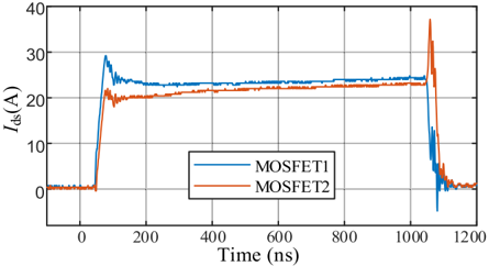
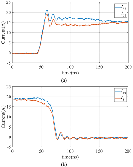
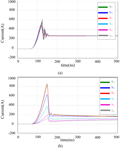
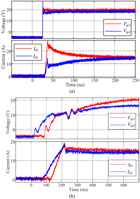
“Fig. 3 is the waveform of the same circuit under different switching speeds [34] which shows that the ringing increases while the di/dt increases from 2 to 6 A/ns.”
§ Parallel Connection of Silicon Carbide MOSFETs -Challenges, Mechanism, and Solutions > C. Challenges Due to Fast Switching Speed
What the sources say
- Not matchedcites [34]
Couldn’t be matched to a paper in Crossref, so it can’t be checked.
plainstates a cause- Asserted: passes — The authors put it forward as true.
- Checkable: passes — It can be checked against evidence.
- Load-bearing: passes — The paper’s conclusions depend on it.
- Based: passes — The paper gives a reason why it holds.
- Not matched
A result the paper states — it cites no source for it, so there is none to check. The quote shows it is in the paper.
In the paper
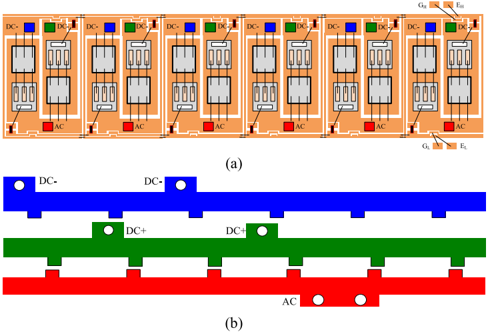
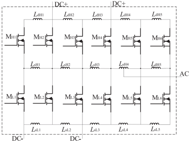
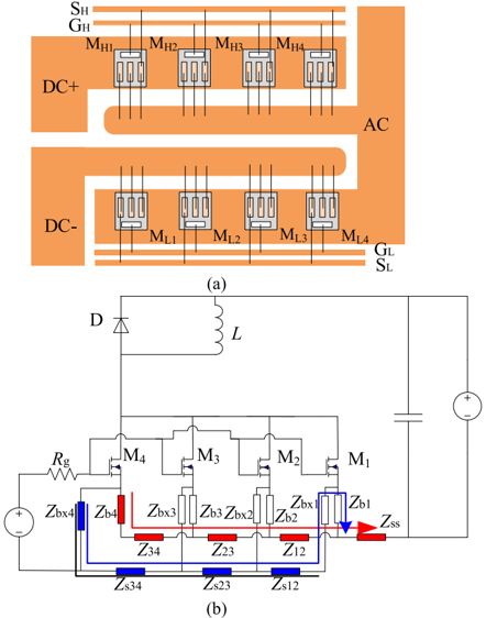
“In this layout, the effective value of L sxL and L dxL is around 1-2 nH considering the magnetic coupling effects.”
§ Parallel Connection of Silicon Carbide MOSFETs -Challenges, Mechanism, and Solutions > V. ANALYSIS AND MODELING OF MULTICHIP POWER MODULE LAYOUTS
plain- Asserted: passes — The authors put it forward as true.
- Checkable: passes — It can be checked against evidence.
- Load-bearing: unclear — It is unclear whether the paper’s conclusions depend on it.
- Based: passes — The paper gives a reason why it holds.
The paper states this without a source or data behind it here, so there is nothing to check it against. The quote shows it is in the paper.
In the paper
“Even though the value of L s4L and L s2L are identical, the di/dt applied on L s2L is more than 3 times that on L s4L .”
§ Parallel Connection of Silicon Carbide MOSFETs -Challenges, Mechanism, and Solutions > A. Current Coupling Effect
plainstates a cause- Asserted: passes — The authors put it forward as true.
- Checkable: passes — It can be checked against evidence.
- Load-bearing: passes — The paper’s conclusions depend on it.
- Based: unclear — It is unclear why the paper says it holds.
A result the paper states — it cites no source for it, so there is none to check. The quote shows it is in the paper.
In the paper
“With a di/dt of 2 kA/μs, the voltage on the parasitic inductance could be around 2-4 V.”
§ Parallel Connection of Silicon Carbide MOSFETs -Challenges, Mechanism, and Solutions > V. ANALYSIS AND MODELING OF MULTICHIP POWER MODULE LAYOUTS
hedgedstates a possible cause- Asserted: passes — The authors put it forward as true.
- Checkable: passes — It can be checked against evidence.
- Load-bearing: passes — The paper’s conclusions depend on it.
- Based: passes — The paper gives a reason why it holds.
54 more claims
Create a free account to see all 151 claims and every source verdict.
- It may state two separate claims as one. 78
- Probably not a substantial claim. 22
Self-check
Percentages, sums and reported differences re-computed from the paper’s own numbers.
Each contradiction between two passages listed here was confirmed by an independent check.
Rated minor: it would not touch a result — a value no result rests on, a p-value that stays on the same side of the significance level, or a conflict that is clerical, resolved elsewhere in the paper, or outside its own findings.
In the paper
§ Parallel Connection of Silicon Carbide MOSFETs -Challenges, Mechanism, and Solutions > B. Dynamic Degree of Imbalance
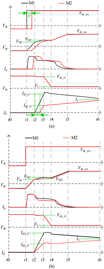
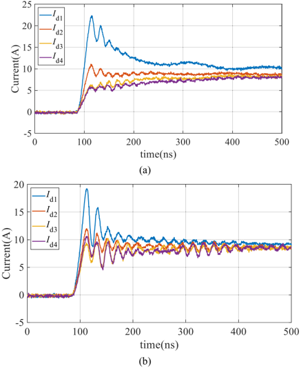
“the gate signal of M1 lags behind M2 for ϕ.”
§ Parallel Connection of Silicon Carbide MOSFETs -Challenges, Mechanism, and Solutions > B. Dynamic Degree of Imbalance
“Since the turn-ON signal of M1 is earlier than M2, the peak current of M1, i.e., I d1 _ t3 , is different from that of M2 I d2 _ t3 .It is apparent that M1 undergoes a higher current than M2.”
Rated minor: it would not touch a result — a value no result rests on, a p-value that stays on the same side of the significance level, or a conflict that is clerical, resolved elsewhere in the paper, or outside its own findings.
In the paper
§ Parallel Connection of Silicon Carbide MOSFETs -Challenges, Mechanism, and Solutions > B. Dynamic Degree of Imbalance
“If the overshoot current is neglected, I d1 _ t3 +I d2 _ t3 = 2I o .”
§ Parallel Connection of Silicon Carbide MOSFETs -Challenges, Mechanism, and Solutions > A. Static Degree of Imbalance
“In (1), n is the total number of MOSFETS in parallel and I o is the total load current.Herein, I o = I d1 +I d2 + …I dn .”
Citations
Cites
Review of Silicon Carbide Power Devices and Their Applications
She, X., Huang, A. Q., Lucia, O., & Ozpineci, B. (2017) · IEEE Transactions on Industrial Electronics · doi:10.1109/tie.2017.2652401 · Cited by 1,773
Review of Solid-State Transformer Technologies and Their Application in Power Distribution Systems
She, X., Huang, A. Q., & Burgos, R. (2013) · IEEE Journal of Emerging and Selected Topics in Power Electronics · doi:10.1109/jestpe.2013.2277917 · Cited by 1,164
Comparison of 6H-SiC, 3C-SiC, and Si for power devices
Bhatnagar, M., & Baliga, B. J. (1993) · IEEE Transactions on Electron Devices · doi:10.1109/16.199372 · Cited by 1,132
High-temperature electronics - a role for wide bandgap semiconductors?
Neudeck, P. G., Okojie, R. S., & Chen, L.-Y. (2002) · Proceedings of the IEEE · doi:10.1109/jproc.2002.1021571 · Cited by 1,080
A Review of GaN on SiC High Electron-Mobility Power Transistors and MMICs
Pengelly, R. S., Wood, S. M., Milligan, J., Sheppard, S. T., & Pribble, W. L. (2012) · IEEE Transactions on Microwave Theory and Techniques · doi:10.1109/tmtt.2012.2187535 · Cited by 1,037
Oh, H., Han, B., McCluskey, P., Han, C., & Youn, B. D. (2014) · IEEE Transactions on Power Electronics · doi:10.1109/tpel.2014.2346485 · Cited by 515
Lelis, A. J., Green, R., Habersat, D. B., & El, M. (2015) · IEEE Transactions on Electron Devices · doi:10.1109/ted.2014.2356172 · Cited by 477
Whitaker, B., Barkley, A., Cole, Z., Passmore, B., Martin, D., McNutt, T. R., Lostetter, A. B., Lee, J. S., & Shiozaki, K. (2013) · IEEE Transactions on Power Electronics · doi:10.1109/tpel.2013.2279950 · Cited by 442
Silicon Carbide Power Transistors: A New Era in Power Electronics Is Initiated
Rąbkowski, J., Peftitsis, D., & Nee, H. (2012) · IEEE Industrial Electronics Magazine · doi:10.1109/mie.2012.2193291 · Cited by 422
Power Conversion With SiC Devices at Extremely High Ambient Temperatures
Funaki, T., Balda, J. C., Junghans, J., Kashyap, A. S., Mantooth, H. A., Barlow, F., Kimoto, T., & Hikihara, T. (2007) · IEEE Transactions on Power Electronics · doi:10.1109/tpel.2007.900561 · Cited by 333
Self-citation
Research works printed but not linked: 5
- regardi, 2020, How Infineon Controls and Assures the Reliability of SiC Based Power Semiconductors
- lin, 2018, Power SiC 2018 Materials Devices and Applications
- friedrichs, 2020, High Performance Coolsic MOSFET Technology With Silicon Like Reliability
- balogh, 2018, Fundamentals of MOSFET and IGBT Gate Driver Circuits
- hofmann, 2018, Evaluation of Potentials for Infineon Sic-Mosfets in Automotive Inverter Applications
Cited by
Items 101–135 of 135
You, X., Hu, Y., Li, X., Ding, Y., Zhu, C., & Lv, F. (2025) · IEEE Energy Conversion Congress and Exposition (ECCE) · doi:10.1109/ecce58356.2025.11259757
Fast thermal reconstruction method for power module based on dilated convolution
Chen, W., Wang, L., Zhang, J., & Zhang, Z. (2025) · IEEE ECCE Asia Downunder · doi:10.1109/ecce-asia63110.2025.11112467
Zhou, Y., Wang, Z., Shen, D., Man, C., Xingshan, L., Hu, G., & Shi, X. (2025) · IEEE Open Journal of Power Electronics · doi:10.1109/ojpel.2025.3647112
Optimization Analysis Research of Station Charging Modules Based on Wide Bandgap Devices
Hu, D., Chen, Z., Zhu, L., Li, T., Yang, W., Li, C., Chen, P., & Li, H. (2025) · International Conference on Power System Technology (POWERCON) · doi:10.1109/powercon66300.2025.11295222
Self-citationAnalysis of Practical Paralleling Limits in SiC MOSFETs under Parameter Mismatch
Jegal, J.-H., Oh, C.-Y., Park, Y., & Lee, J.-P. (2025) · International Conference on Electrical Machines and Systems (ICEMS) · doi:10.23919/icems66262.2025.11317284
Kumar, P., & Nair, H. S. (2025) · IEEE International Conference on Green Industrial Electronics and Sustainable Technologies (GIEST) · doi:10.1109/giest66547.2025.11387725
Efficiency Optimization of a 7 kW EV Charger Based on a Coupled Inductor Design
Ning, N., Yang, D., Cao, X., & Wang, Z. (2026) · World Electric Vehicle Journal · doi:10.3390/wevj17030151
Yan, X., Deng, X., Hao, W., Zeng, X., Li, X., & Zhang, B. (2026) · Semiconductor Science and Technology · doi:10.1088/1361-6641/ae6367
From Silicon to SiC: Transforming EV Battery Managements
Gupta, K., Thareja, S., Biswas, M., & Kansal, N. (2026) · International Conference on Computing, Electronics & Communications Engineering (iCCECE) · doi:10.1109/iccece69715.2026.11492822
Yan, Z., Liu, G., Zhao, H., & Munk‐Nielsen, S. (2026) · Conference proceedings/Conference proceedings - IEEE Applied Power Electronics Conference and Exposition · doi:10.1109/apec51134.2026.11516917
Duty Cycle Optimization for Active Thermal Compensation of Parallel Connected SiC MOSFETs
Deldimos, D., Stella, F., Piccioni, A., & Pellegrino, G. (2026) · Conference proceedings/Conference proceedings - IEEE Applied Power Electronics Conference and Exposition · doi:10.1109/apec51134.2026.11516769
Evaluation of body-diode degradation in 4H-SiC VMOSFETs under high-current-density stress
Masuda, T., Ikeda, T., Hara, Y., Saito, Y., Nishiguchi, T., Harada, S., Furumai, M., Kiyama, T., & Watanabe, H. (2026) · Japanese Journal of Applied Physics · doi:10.35848/1347-4065/ae70e1
Song, R., Chen, G., Li, Z., & Zhang, Z. C. (2026) · IEEE Transactions on Power Electronics · doi:10.1109/tpel.2026.3699684
A Two-Stage Turn-On Crosstalk Model for SiC MOSFETs in Half-Bridge Circuits
Yuan, Z., Li, H., Zhang, M., Yang, Z., Wang, H., Wang, X., & Ding, L. (2026) · IEEE Transactions on Power Electronics · doi:10.1109/tpel.2026.3701449
Self-citationDetecting Asymmetries Within Multi-Chip SiC Power Modules by Means of the Kelvin Source
Müller, J., Lutzen, H., Buchholz, T., Peters, J.-H., Saito, W., & Kaminski, N. (2026) · IEEE International Symposium on Power Semiconductor Devices and ICs/Proceedings of the International Symposium on Power Semiconductor Devices & ICs/Proceedings of the ... International Symposium on Power Semiconductor Devices & ICs/Proceedings of the ... International Symposium on Power Semiconductor Devices and ICs · doi:10.1109/ispsd64561.2026.11553646
Li, D., Chang, X., Zhang, K., Huang, Y., 刘学杰, & Ren, X. (2026) · Asia Energy and Electrical Engineering Symposium (AEEES) · doi:10.1109/aeees69423.2026.11556648
Man, C., Zhou, Y., Liang, K., Zhao, J., He, C., Wu, J., Kong, W., & Wang, Z. (2026) · IEEE Transactions on Power Electronics · doi:10.1109/tpel.2026.3704943
Controllable Demagnetization Strategy for Magnet Power Supply Based on Linear-Region MOSFETs
Yin, H., Wu, Y., Lü, J., Li, J., He, B., Xu, L., Tian, Y., Wang, P., Liu, N., Ma, X., et al. (2026) · IEEE Transactions on Plasma Science · doi:10.1109/tps.2026.3708729
Guo, T., Shao, S., Zhang, M., Jiang, Y., & Zhang, J. (2026) · IEEE Transactions on Power Electronics · doi:10.1109/tpel.2026.3713968
Comparative Evaluation of Gate Driving Schemes for Paralleled 2.3 kV SiC MOSFET Power Modules
Qi, N., Liu, G., Zhao, H., Jørgensen, A. B., & Munk‐Nielsen, S. (2026) · International Power Electronics Conference (IPEC) · doi:10.23919/ipec-nagasaki2026-ec64663.2026.11597166
Influence of gate resistance and parasitic components on current sharing in parallel GaN MOSFETs
Alam, M., & Kumar, B. A. (2026) · Sadhana · doi:10.1007/s12046-026-03211-8
Chen, Z., Sun, L., Qi, Z., Tang, X.-Y., Song, Q., & Zhang, Y. (2026) · IEEE Transactions on Power Electronics · doi:10.1109/tpel.2026.3718052
Feasible Operating Boundary Extraction for MW‐Class SiC Inverters in High‐Speed Drives
Upadhyay, D., Mattsson, A., & Peltoniemi, P. (2026) · IET Power Electronics · doi:10.1049/pel2.70304
An Advanced Radio Frequency Power Supply for the Quadrupole with Thermostable Feedback
He, A., Zhang, K., Lv, J., Zhou, X., Liu, L., & Li, M. (2026) · International Conference on Electronics Technology (ICET) · doi:10.1109/icet69987.2026.11659255
Source-feedback and thermal-uniformity co-design of a multi-chip SiC MOSFET module
车黎明, Yang, S., Li, C., Liao, S., Mao, Y., & Lei, G. (2026) · Results in Engineering · doi:10.1016/j.rineng.2026.113856
Oscillation Mechanism in Parallel-Connected SiC Power MOSFETsPreprint
Spitaleri, M. G., Scelba, G., & Iannuzzo, F. (2026) · SSRN Electronic Journal · doi:10.2139/ssrn.7423663
Active Thermal Balancing Strategy for Direct Parallel Connection of SiC MOSFETs
Deldimos, D., Stella, F., Piccioni, A., & Pellegrino, G. (2026) · IEEE Open Journal of Industry Applications · doi:10.1109/ojia.2026.3731352
A current-sharing circuit for paralleled SiC MOSFETs based on active variable gate resistance
Meng, Q., Cao, Y., Li, X., & Cai, Z. (2026) · International Symposium on Semiconductor and Electronic Technology (ISSET) · doi:10.1109/isset70600.2026.11682631
Design and Performance Evaluation of a Cu-Clip-Interconnected Half-Bridge SiC Power Module
Meng, Y., Yan, H., Liu, C., & Li, W. (2026) · International Conference on Electronic Packaging Technology (ICEPT) · doi:10.1109/icept71373.2026.11690012
Yari, K., Mehrabi, A., Poelma, R. H., Du, S., van Driel, W., & Zhang, G. (2026) · IEEE Open Journal of Power Electronics · doi:10.1109/ojpel.2026.3747467
Parallel Connection of SiC MOSFETs Under Circuital and Parametric Mismatch
Raciti, A., Catalisano, G., Abbatelli, L., & Parisi, C. (2026) · Energy Conversion Congress and Expo Europe (ECCE Europe) · doi:10.1109/ecceeurope67962.2026.11738006
Evalaution of 1200 V Wide Bandgap Hybrid Switches: SiC MOSFET vs GaN e-HEMT/Si-IGBT
Zhang, M., Liu, X., Ayala, H., Jahdi, S., Yuan, X., & Alatise, O. M. (2026) · IEEE Workshop on Wide Bandgap Power Devices and Applications in Europe (WiPDA Europe) · doi:10.1109/wipdaeurope69886.2026.11746958
Feedback controlled active gate driving of parallel trench SiC-MOSFET devices
Tripathi, R. N., & Omura, I. (2026) · Microelectronic Engineering · doi:10.1016/j.mee.2026.112525
Wang, X., Leung, T., Jahdi, S., & Stark, B. H. (2026) · Explore Bristol Research · doi:10.30420/566716388
Self-citationLi, Y., Yuan, X., Xiu, D., Ning, Y., Zhang, Y., Jahdi, S., Tan, G., Wang, K., & Zhou, W. (2026) · IET Power Electronics · doi:10.1049/pel2.70242
Metadata
- Authors
- Li, H., Zhao, S., Wang, X., Ding, L., & Mantooth, H. A.
- Affiliations
- Hefei University of Technology (CN)
- KTH Royal Institute of Technology (SE)
- University of Arkansas at Fayetteville (US)
- Venue
- IEEE Transactions on Power Electronics
- Published
- 2023-08
- Volume
- 38
- Issue
- 8
- Pages
- 9731-9749
- ISSN
- 0885-8993 (ISSN-L)
- 1941-0107
- OpenAlex
- W4377291033
- Cited by
- 135
- References
- 121
- Citations by year
- 2026: 35 · 2025: 65 · 2024: 28 · 2023: 7
- FWCI
- 9.51
- Type
- journal article
- Language
- en
- Open access
- hybrid
- doi.org
- Locations
- IEEE Transactions on Power Electronics (publishedVersion, cc-by)
- VBN Forskningsportal (Aalborg Universitet) (publishedVersion, cc-by)
- Funders
- Anhui Natural Science Foundation (2208085QE164)
- Higher Education Discipline Innovation Project (BP0719039)
- Topics
- Physical Sciences › Engineering › Electrical and Electronic Engineering › Silicon Carbide Semiconductor Technologies
- Physical Sciences › Engineering › Electrical and Electronic Engineering › Advanced DC-DC Converters
- Physical Sciences › Engineering › Electrical and Electronic Engineering › Multilevel Inverters and Converters
- Keywords
- SiC MOSFET, parallel connection, current imbalance, current sharing, parasitic parameters, power semiconductor reliability, high-speed switching
About these checks
Registry, retraction, Cites and statistics results are computed, not judged, with one exception: a printed reference that no index lists is read once by a model before it counts as a citation error. Claims are extracted by a model and kept only when their quote appears verbatim in the text; each cited source is then checked, with a model’s help, for whether it says what the claim relies on. Those verdicts can be wrong — read the claim’s quote and the cited source before relying on one.
A language model drew the claims from the paper on 2026-11-12, under version 3 of the claim definition (model deepseek-v4.1-flash, prompt extract-v3).
A second model labelled each claim on 2026-11-12 (model jev-1.13-20260917, definition revision gold-guideline-v0.2).
Statistics and arithmetic are recomputed, not judged.
Confidence bands are shown only for fields calibrated on our annotated test set. None is calibrated yet, so no band is shown.
What counts as a claim ›How we measure confidence ›How we check this ›
Are you an author, or do you see a problem with this page? Request a review
Data sources
Bibliographic data: Semantic Scholar, OpenAlex, Crossref.
Contains information from the Semantic Scholar Academic Graph Datasets, made available under the ODC Attribution License (ODC-BY 1.0).
Semantic Scholar’s data is described in: Kinney, R., et al. (2023). The Semantic Scholar Open Data Platform. arXiv:2301.10140.
