

The DOI matches its Crossref record; the references it cites are not checked yet.
A Multiplexable Op-Amp Interface for Accurate Readout of Remote Resistive Sensors
Open accessAbstract
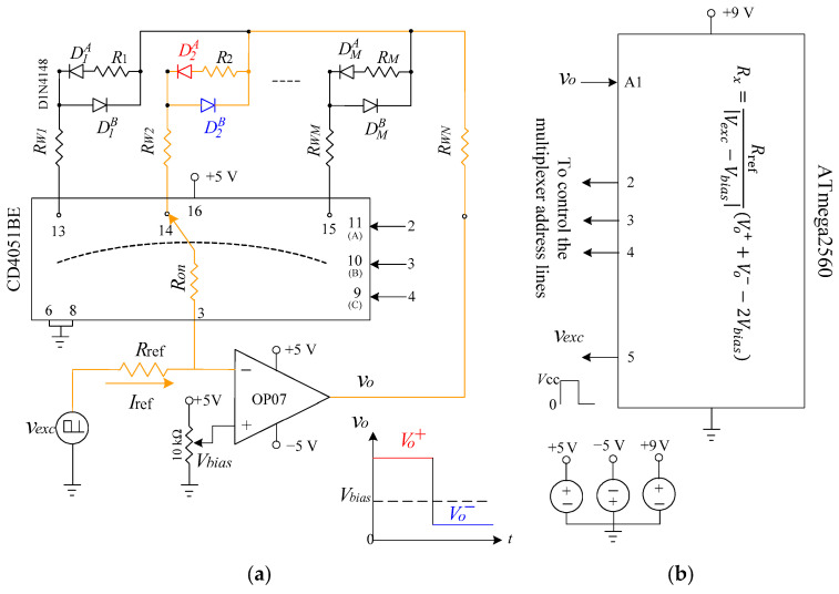
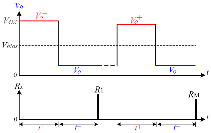
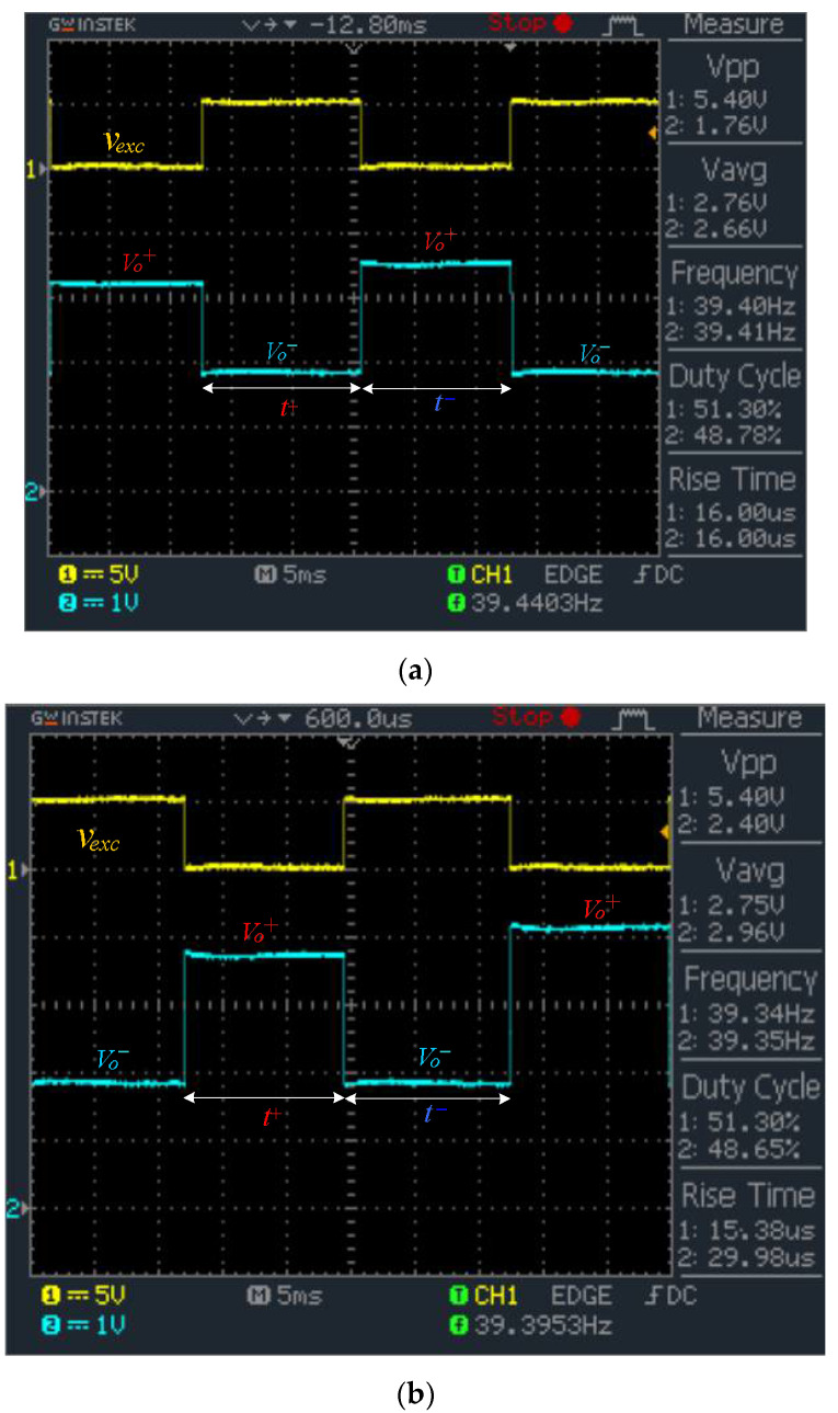
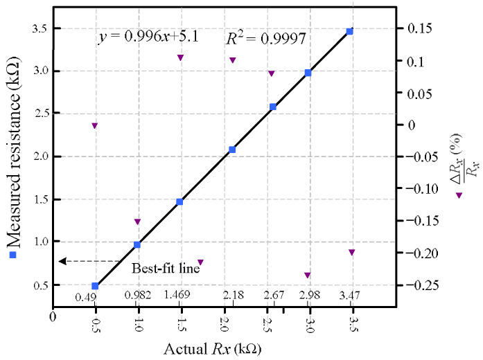
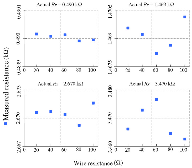
This paper presents a compact and accurate readout circuit for remote two-wire resistive sensors, based on an inverting operational amplifier with a fixed bias voltage, diode steering, and unidirectional square-wave excitation generated by a microcontroller. The proposed method determines the sensor resistance by directly sampling two steady-state voltage plateaus at the op-amp output during alternating excitation phases. This approach enables fast, lead-wire-insensitive measurements without the need for analog filtering or precise PWM duty-cycle control. The architecture supports sensor array multiplexing via analog switches, allowing scalable, low-power implementation. Experimental results demonstrate a maximum relative error of 0.23% across a wide resistance range (0.5–3.5 kΩ), confirming the method’s suitability for low-cost, embedded, and remote sensing applications.
Overview
The claims and statistics of this paper haven’t been checked yet.
Run the check — free, no account needed. It reads the open-access text and checks the sources it cites.
Integrity signals
Registry
Cites
Statistics
Figures
Verification
Claims the paper makes
The claims and statistics of this paper haven’t been checked yet.
Run the check — free, no account needed. It reads the open-access text and checks the sources it cites.
Self-check
Percentages, sums and reported differences re-computed from the paper’s own numbers.
The self-check needs the paper’s full text.
Citations
The citation lists haven’t been fetched yet
References 15 · Cited by 3
Research works printed but not linked: 17
- Loconsole, D., Elia, M., Conversa, G., De Lucia, B., Cristiano, G., and Elia, A. (2025). Soil Moisture Sensing Technologies: Principles, Applications, and Challenges in Agriculture. Agronomy, 15. · DOI
- Kaunkid, 2024, Resistive Measurement Method for MQ Sensors Based on ADCs of Microcontrollers, IEEE Access, 12, 144364, 10.1109/ACCESS.2024.3472697 · DOI · Paper page
- Shu, 2015, A New Approach for Readout of Resistive Sensor Arrays for Wearable Electronic Applications, IEEE Sens. J., 15, 442, 10.1109/JSEN.2014.2333518 · DOI
- Liu, L., Cheng, W., and Kuo, H.W. (2025). A Narrative Review on Smart Sensors and IoT Solutions for Sustainable Agriculture and Aquaculture Practices. Sustainability, 17. · DOI
- Nagarajan, 2017, Improved single-element resistive sensor-to-microcontroller interface, IEEE Trans. Instrum. Meas., 66, 2736, 10.1109/TIM.2017.2712918 · DOI
- Reverter, F. (2024). Two proposals of a simple analog conditioning circuit for remote resistive sensors with a three-wire connection. Sensors, 24. · DOI · Paper page
- Khamsen, 2025, Simplified Three-Wire and Four-Wire Interface for Resistive Sensor Measurement Using Microcontroller ADCs, IEEE Trans. Instrum. Meas., 74, 9523710, 10.1109/TIM.2025.3578689 · DOI
- Elangovan, 2024, A Novel Triple-Slope-Based Digital Measurement Platform for Three-Wire Connected Resistive Sensors, IEEE Trans. Instrum. Meas., 73, 2004103, 10.1109/TIM.2024.3411132 · DOI
- Elangovan, 2023, An efficient digital readout for four-lead resistance thermometers, IEEE Sensors Lett., 7, 6009504
- Mathew, 2023, Accurate Interface Schemes for Resistance Thermometers with Lead Resistance Compensation, IEEE Trans. Instrum. Meas., 72, 2005904, 10.1109/TIM.2023.3291739 · DOI
- Reverter, F. (2023). A front-end circuit for two-wire connected resistive sensors with a wire-resistance compensation. Sensors, 23. · DOI
- Jittakort, J., and Aurasopon, A. (2025). A Digitally Controlled Adaptive Current Interface for Accurate Measurement of Resistive Sensors in Embedded Sensing Systems. J. Sens. Actuator Netw., 14. · DOI · Paper page
- Czaja, 2024, Simple Measurement Method for Resistive Sensors Based on ADCs of Microcontrollers, IEEE Sens. J., 24, 2996, 10.1109/JSEN.2023.3341214 · DOI · Paper page
- 2024, A Method of Tactile Resistive Sensor Array Calibration, IFAC-PapersOnLine, 58, 37
- Zhang, 2023, Adaptive Readout Approaches of Resistive Sensor Array for Wearable Electronics Applications, Measurement, 221, 113524, 10.1016/j.measurement.2023.113524 · DOI · Paper page
- Norouzi, 2024, High Accuracy Approach for Crosstalk Effects Compensation on 2-D Resistive Sensor Array Readouts, IEEE Sens. J., 24, 6824, 10.1109/JSEN.2024.3353071 · DOI
- Wu, 2021, All-Silicon Microdisplay Using Efficient Hot-Carrier Electroluminescence in Standard 0.18μm CMOS Technology, IEEE Electron Device Lett., 42, 541, 10.1109/LED.2021.3059781 · DOI
Metadata
- Authors
- Kuankid, S., Jittakort, J., & Aurasopon, A.
- Affiliations
- Nakhon Pathom Rajabhat University (TH)
- Rajamangala University of Technology (TH)
- Mahasarakham University (TH)
- Corresponding author
- Aurasopon, Apinan
- Venue
- Sensors
- Publisher
- MDPI AG
- Published
- 2026-01-10
- Volume
- 26
- Issue
- 2
- Pages
- 461
- ISSN
- 1424-8220 (ISSN-L)
- PMC
- PMC12846225
- OpenAlex
- W7122763239
- Cited by
- 3
- References
- 15
- Citations by year
- 2026: 3
- FWCI
- 11.29
- Type
- journal article
- Language
- en
- Open access
- gold
- doi.org
- Licence
- Locations
- Sensors (publishedVersion, cc-by)
- PubMed (publishedVersion)
- PubMed Central (publishedVersion, cc-by)
- DOAJ (DOAJ: Directory of Open Access Journals) (submittedVersion, cc-by-sa)
- Funders
- Mahasarakham University
- Topics
- Physical Sciences › Physics and Astronomy › Instrumentation › Sensor Technology and Measurement Systems
- Physical Sciences › Engineering › Electrical and Electronic Engineering › Analog and Mixed-Signal Circuit Design
- Physical Sciences › Physics and Astronomy › Instrumentation › Advanced Sensor Technologies Research
- Keywords
- analog switches, low-power readout, embedded sensing
About these checks
Registry, retraction, Cites and statistics results are computed, not judged, with one exception: a printed reference that no index lists is read once by a model before it counts as a citation error. Claims are extracted by a model and kept only when their quote appears verbatim in the text; each cited source is then checked, with a model’s help, for whether it says what the claim relies on. Those verdicts can be wrong — read the claim’s quote and the cited source before relying on one.
Statistics and arithmetic are recomputed, not judged.
Confidence bands are shown only for fields calibrated on our annotated test set. None is calibrated yet, so no band is shown.
What counts as a claim ›How we measure confidence ›How we check this ›
Are you an author, or do you see a problem with this page? Request a review
How to cite
Cite CoChat for the checks on this page, and the paper for its own findings.
- This page
- CoChat. (2026). Citation check: A Multiplexable Op-Amp Interface for Accurate Readout of Remote Resistive Sensors. https://app.cochat.ai/papers/10.3390/s26020461
- The paper
- Kuankid, S., Jittakort, J., & Aurasopon, A. (2026). A Multiplexable Op-Amp Interface for Accurate Readout of Remote Resistive Sensors. Sensors. https://doi.org/10.3390/s26020461
