

The DOI matches its Crossref record; 47 of the 47 references it cites were found in a registry or an index.
All-printed nanomembrane wireless bioelectronics using a biocompatible solderable graphene for multimodal human-machine interfaces
Open accessAbstract
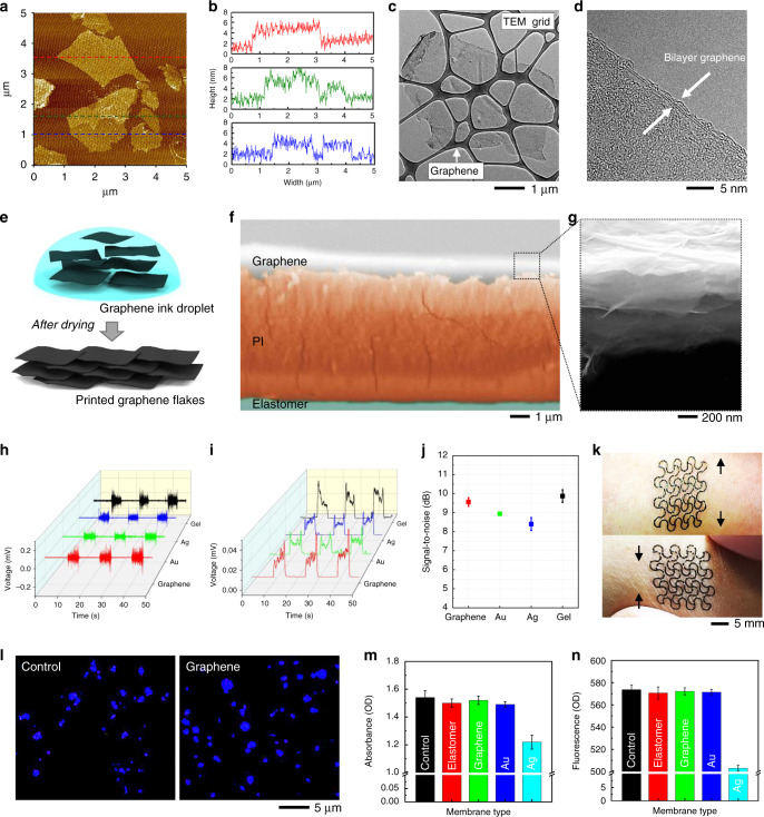
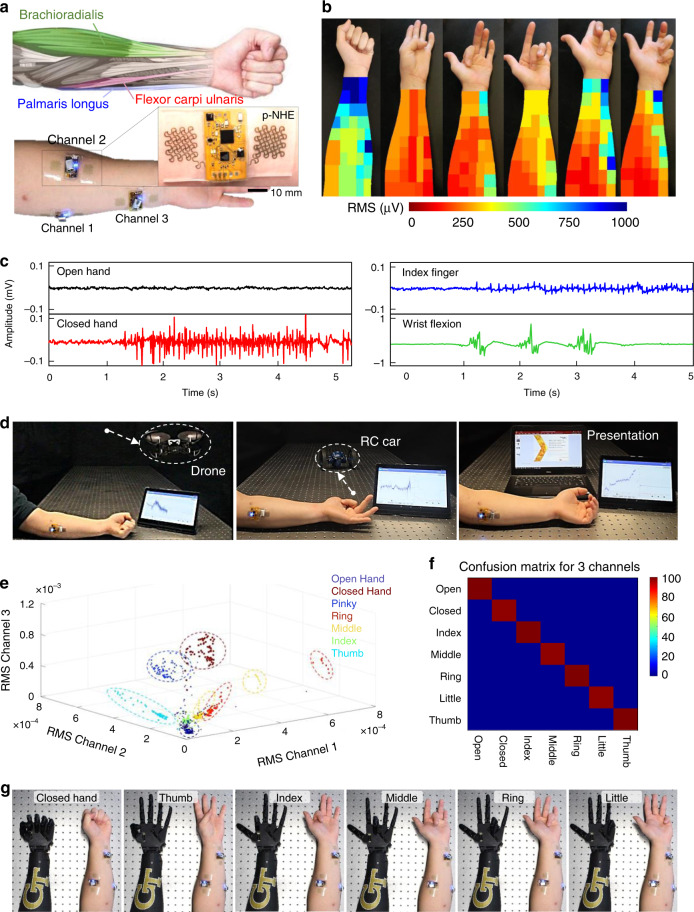
Recent advances in nanomaterials and nano-microfabrication have enabled the development of flexible wearable electronics. However, existing manufacturing methods still rely on a multi-step, error-prone complex process that requires a costly cleanroom facility. Here, we report a new class of additive nanomanufacturing of functional materials that enables a wireless, multilayered, seamlessly interconnected, and flexible hybrid electronic system. All-printed electronics, incorporating machine learning, offers multi-class and versatile human-machine interfaces. One of the key technological advancements is the use of a functionalized conductive graphene with enhanced biocompatibility, anti-oxidation, and solderability, which allows a wireless flexible circuit. The high-aspect ratio graphene offers gel-free, high-fidelity recording of muscle activities. The performance of the printed electronics is demonstrated by using real-time control of external systems via electromyograms. Anatomical study with deep learning-embedded electrophysiology mapping allows for an optimal selection of three channels to capture all finger motions with an accuracy of about 99% for seven classes.
Overview
The claims and statistics of this paper haven’t been checked yet.
Free: it reads the open-access text and checks the first 5 claims that cite a source we can check. Create a free account to check every claim.
Integrity signals
Registry
Cites
Statistics
Figures


Verification
Claims the paper makes
The claims and statistics of this paper haven’t been checked yet.
Free: it reads the open-access text and checks the first 5 claims that cite a source we can check. Create a free account to check every claim.
Claims other papers make about this one
Each is checked against this paper’s own text: does it say what the citing paper says it does?
The source backs part of the claim, not all of it — or backs it for a different population, condition or comparison.
In the citing paper
“However, the long-term impact of these materials on the human body remains an uncertainty limiting the actual long-term commercial application of the devices in HMI.”
From Flexible Electronics and Devices as Human–Machine Interfaces for Medical Robotics (2022) · cites this paper as [607]
Experimental — accuracy not yet measured
Self-check
Percentages, sums and reported differences re-computed from the paper’s own numbers.
The self-check needs the paper’s full text.
Citations
Cites
Fully integrated wearable sensor arrays for multiplexed in situ perspiration analysis
Gao, W., Emaminejad, S., Nyein, H. Y. Y., Challa, S., Chen, K., Peck, A., Fahad, H. M., Ota, H., Shiraki, H., Kiriya, D., et al. (2016) · Nature · doi:10.1038/nature16521 · Cited by 5,087
Lim, H., Kim, H. S., Qazi, R., Kwon, Y., Jeong, J., & Yeo, W. (2020) · Advanced Materials · doi:10.1002/adma.201901924 · Cited by 1,002
Self-citationChoi, S., Han, S. I., Jung, D., Hwang, H. J., Lim, C., Bae, S., Park, O. K., Tschabrunn, C. M., Lee, M., Bae, S. Y., et al. (2018) · Nature Nanotechnology · doi:10.1038/s41565-018-0226-8 · Cited by 984
Park, M., Im, J., Shin, M., Min, Y., Park, J., Cho, H., Park, S., Shim, M.-B., Jeon, S., Chung, D.-Y., et al. (2012) · Nature Nanotechnology · doi:10.1038/nnano.2012.206 · Cited by 919
Self-citationMonitoring of the central blood pressure waveform via a conformal ultrasonic device
Wang, C., Li, X., Hu, H., Zhang, L., Huang, Z., Lin, M., Zhang, Z., Yin, Z., Huang, B., Gong, H., et al. (2018) · Nature Biomedical Engineering · doi:10.1038/s41551-018-0287-x · Cited by 895
Printable elastic conductors with a high conductivity for electronic textile applications
Matsuhisa, N., Kaltenbrunner, M., Yokota, T., Jinno, H., Kuribara, K., Sekitani, T., & Someya, T. (2015) · Nature Communications · doi:10.1038/ncomms8461 · Cited by 869
Imani, S., Bandodkar, A. J., Mohan, A. M. V., Kumar, R., Yu, S., Wang, J., & Mercier, P. P. (2016) · Nature Communications · doi:10.1038/ncomms11650 · Cited by 861
Molecular toxicity mechanism of nanosilver
McShan, D., Ray, P. C., & Yu, H. (2014) · Journal of Food and Drug Analysis · doi:10.1016/j.jfda.2014.01.010 · Cited by 762
Printable elastic conductors by in situ formation of silver nanoparticles from silver flakes
Matsuhisa, N., Inoue, D., Zalar, P., Jin, H., Matsuba, Y., Itoh, A., Yokota, T., Hashizume, D., & Someya, T. (2017) · Nature Materials · doi:10.1038/nmat4904 · Cited by 750
Graphene Electronic Tattoo Sensors
Kabiri Ameri, S., Ho, R., Jang, H., Tao, L., Wang, Y., Wang, L., Schnyer, D. M., Akinwande, D., & Lu, N. (2017) · ACS Nano · doi:10.1021/acsnano.7b02182 · Cited by 669
Cited by
Flexible Electronics and Devices as Human–Machine Interfaces for Medical Robotics
Heng, W., Solomon, S., & Gao, W. (2022) · Advanced Materials · doi:10.1002/adma.202107902 · Cited by 609
Wearable chemical sensors for biomarker discovery in the omics era
Sempionatto, J. R., Lasalde-Ramírez, J. A., Mahato, K., Wang, J., & Gao, W. (2022) · Nature Reviews Chemistry · doi:10.1038/s41570-022-00439-w · Cited by 613
All-printed soft human-machine interface for robotic physicochemical sensing
Yu, Y., Li, J., Solomon, S. A., Min, J., Tu, J., Guo, W., Xu, C., Song, Y., & Gao, W. (2022) · Science Robotics · doi:10.1126/scirobotics.abn0495 · Cited by 365
Wang, H., Zhou, R., Li, D., Zhang, L., Ren, G., Wang, L., Liu, J., Wang, D., Tang, Z., Lu, G., et al. (2021) · ACS Nano · doi:10.1021/acsnano.1c00259 · Cited by 364
2D Materials in Flexible Electronics: Recent Advances and Future Prospectives
Katiyar, A. K., Hoang, A. T., Xu, D., Hong, J., Kim, B. J., Ji, S., & Ahn, J.-H. (2024) · Chemical Reviews · doi:10.1021/acs.chemrev.3c00302 · Cited by 363
Metadata
- Authors
- Kwon, Y.-T., Kim, Y.-S., Kwon, S., Mahmood, M., Lim, H.-R., Park, S.-W., Kang, S.-O., Choi, J. J., Herbert, R., Jang, Y. C., Choa, Y.-H., & Yeo, W.-H.
- Affiliations
- Georgia Institute of Technology (US)
- Hanyang University (KR)
- Corresponding author
- Yeo, Woon-Hong
- ORCID
- Venue
- Nature Communications
- Published
- 2020-07-10
- Volume
- 11
- Issue
- 1
- Pages
- 3450-3450
- ISSN
- 2041-1723 (ISSN-L)
- PMC
- PMC7351733
- OpenAlex
- W3040932193
- Semantic Scholar
- 090841e4c7df568232565e287bcc0be05d586aea
- Cited by
- 233
- References
- 47
- Citations by year
- 2026: 26 · 2025: 41 · 2024: 50 · 2023: 36 · 2022: 39 · 2021: 34 · 2020: 7
- FWCI
- 9.95
- Type
- journal article
- Language
- en
- Open access
- gold
- doi.org
- Licence
- cc-by
- creativecommons.org/licenses/by/4.0 (tdm)
- creativecommons.org/licenses/by/4.0 (vor)
- Locations
- Nature Communications (publishedVersion, cc-by)
- PubMed Central (publishedVersion, cc-by)
- PubMed (publishedVersion)
- RePEc: Research Papers in Economics (submittedVersion)
- DOAJ (DOAJ: Directory of Open Access Journals) (submittedVersion, cc-by-sa)
- Funders
- Georgia Research Alliance
- U.S. Department of Health & Human Services | National Institutes of Health (R21AG064309)
- National Research Foundation of Korea (2016M3A7B4900044)
- National Science Foundation (ECCS-1542174)
- Topics
- Physical Sciences › Engineering › Electrical and Electronic Engineering › Nanomaterials and Printing Technologies
- Physical Sciences › Engineering › Biomedical Engineering › Advanced Sensor and Energy Harvesting Materials
- Life Sciences › Neuroscience › Cellular and Molecular Neuroscience › Neuroscience and Neural Engineering
- Keywords
- printed electronics, graphene, flexible electronics, human-machine interaction, electromyography, muscle activity sensing, wearable electronics, finger motion recognition, biocompatibility, anti-oxidation
- MeSH terms
- Wearable Electronic Devices, Electric Conductivity, Electronics, Graphite, Humans, Biosensing Techniques, Nanostructures, Wireless Technology
About these checks
Registry, retraction, Cites and statistics results are computed, not judged, with one exception: a printed reference that no index lists is read once by a model before it counts as a citation error. Claims are extracted by a model and kept only when their quote appears verbatim in the text; each cited source is then checked, with a model’s help, for whether it says what the claim relies on. Those verdicts can be wrong — read the claim’s quote and the cited source before relying on one.
Statistics and arithmetic are recomputed, not judged.
Confidence bands are shown only for fields calibrated on our annotated test set. None is calibrated yet, so no band is shown.
What counts as a claim ›How we measure confidence ›How we check this ›
Are you an author, or do you see a problem with this page? Request a review
How to cite
Cite CoChat for the checks on this page, and the paper for its own findings.
- This page
- CoChat. (2026). Citation check: All-printed nanomembrane wireless bioelectronics using a biocompatible solderable graphene for multimodal human-machine interfaces. https://app.cochat.ai/papers/10.1038/s41467-020-17288-0
- The paper
- Kwon, Y.-T., Kim, Y.-S., Kwon, S., Mahmood, M., Lim, H.-R., Park, S.-W., Kang, S.-O., Choi, J. J., Herbert, R., Jang, Y. C., Choa, Y.-H., & Yeo, W.-H. (2020). All-printed nanomembrane wireless bioelectronics using a biocompatible solderable graphene for multimodal human-machine interfaces. Nature Communications. https://doi.org/10.1038/s41467-020-17288-0
Data sources
Bibliographic data: Semantic Scholar, OpenAlex, Crossref.
Contains information from the Semantic Scholar Academic Graph Datasets, made available under the ODC Attribution License (ODC-BY 1.0).
Semantic Scholar’s data is described in: Kinney, R., et al. (2023). The Semantic Scholar Open Data Platform. arXiv:2301.10140.
