

Self-powered electro-tactile system for virtual tactile experiences
Open accessThe DOI matches its Crossref record; 43 of the 43 references it cites were found in a registry or an index; 6 of the 52 sources its claims cite were checked for support.
Abstract
TENG-based electro-tactile system has the advantages of simple system, low cost, and zero power consumption.
Overview
CoChat Summary
TL;DR
The paper presents a self-powered, skin-integrated electro-tactile (ET) system that uses a triboelectric nanogenerator (TENG) array to drive noncontact microgap discharge on ball-shaped electrodes, producing virtual tactile sensations without an external power supply. It demonstrates pattern reproduction, spatial resolution, and integration into wearable/protective-suit concepts.
Key findings
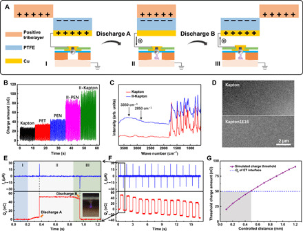
- A TENG unit of 20 × 20 mm can trigger ET discharge at a controlled electrode–skin distance of 0.5 mm; the optimal painless perceptible range is 0.3 to 0.5 mm, with induced current kept below 25 μA.
- Ion bombardment improved triboelectric output: II-Kapton showed the highest transferred charge (~105 nC) with PTFE, higher than II-PEN (~70 nC) and other tested materials.
- The ET interface achieved spatial resolution of about 3 mm on the index finger and 10 mm on the forearm; 80% of participants could recognize a 10-mm two-point stimulus on the forearm.
- A 21-electrode on-skin ET interface reproduced spatial patterns and motion traces, and a fully integrated contact-separation TENG unit produced about 25 μA discharge current and ~44 nC transferred charge.
Methods
- The system combined a sliding-mode TENG array with a skin-integrated ET interface of ball-shaped tin electrodes (0.5 mm diameter, 15 mm spacing) encapsulated in a wearable band; discharge occurred through laser-drilled holes in VHB tape at controlled distances.
- TENG materials were tested with PTFE against Kapton, PET, PEN, ion-bombarded PEN, and ion-bombarded Kapton; ion bombardment used 50-keV He ions at 1 × 10^16 ions/cm².
- Human tests involved 10 participants (six males, four females, aged 22–35) who rated pain under controlled distances from 1.5 to 0.2 mm and performed two-point discrimination on the index finger and forearm.
Limitations
- The paper states that at high skin humidity (100%) caused by excessive sweat, charge leakage cannot be neglected; a cotton tissue between VHB tape and skin is suggested to absorb sweat.
- The paper states that the stretchable silicone-rubber ET interface showed lower discharge current than the nonstretchable version, possibly due to energy loss from high resistance.
- Evident from the text: human testing used a small sample (10 participants) who were the authors and three other laboratory members, so the perceptual results are not from a broad or independent participant pool.
Model-written summary. Check it against the paper before relying on it.
Integrity signals
Registry
Cites
Statistics
Figures



Verification
Claims the paper makes
3 Valid · 5 Not valid · 18 Not checked · 123 Own results and interpretations
The cited sources support only part of this claim — read each source’s verdict below.
In the paper
“It is possible to lower down voltage and current value for electrostimulation by using needle electrodes to release signal under the epidermis”
§ Self-powered electro-tactile system for virtual tactile experiences > INTRODUCTION
What the sources say
- Partly supportedcites [15] M. Tezuka, N. Kitamura, K. Tanaka, N. Miki, Presentation of various tactile sensations using micro-needle electrotactile display. PLOS ONE 11, e0148410 (2016). 26845336 PMC4742061 sourceExperimental — accuracy not yet measured
The voltage half of the claim is squarely supported: the Introduction and Abstract state that the micro-needle electrodes penetrate the high-impedance stratum corneum (the outermost layer of the epidermis, 100 kΩ·m) and thereby 'drastically reduced the required voltage, i.e., the threshold voltage', quantified in 4.1 (flat-electrode M = 72.29 V vs needle devices M = 19.03 V / 11.15 V). However, our copy reports no reduction in current: every measurement in 3.2, 3.3 and 4.1 is a voltage (Vth, Vpain), and the only mention of current (Introduction) concerns the path of the stimulating currents through shallow vs deep receptors, not their magnitude. The claim's 'and current' component is therefore not attributable to this source. (LLM, conf=0.80)
- Not checked yetcites [16] M. Tezuka, N. Kitamura, N. Miki, Micro-needle electro-tactile display, 28th IEEE International Conference on Micro Electro Mechanical Systems (MEMS) (Estoril, 2015), pp. 5781–5784. 26737606 source
- Not checked yetcites [17] N. Kitamura, J. Chim, N. Miki, Micro-needle electrode array for electro tactile display, in Transducers (Barcelona, Spain, 2013), pp. 106–107. source
- Not checked yetcites [18] M. Ortiz-Catalan, E. Mastinu, P. Sassu, O. Aszmann, R. Branemark, Self-contained neuromusculoskeletal arm prostheses. N. Engl. J. Med. 382, 1732– 1738 (2020). 32348644 source
hedgedstates a possible cause- Asserted: passes — The authors put it forward as true.
- Checkable: passes — It can be checked against evidence.
- Load-bearing: unclear — It is unclear whether the paper’s conclusions depend on it.
- Based: passes — The paper gives a reason why it holds.
- Partly supported
The cited sources support only part of this claim — read each source’s verdict below.
In the paper
“The ultrahigh electrostatic field provided by TENG is enough to stimulate skin through microgap discharge without direct contact or penetration (27–29).”
§ Self-powered electro-tactile system for virtual tactile experiences > INTRODUCTION
What the sources say
- Not checked yetcites [27] J. Nie, X. Chen, Z. L. Wang, Electrically responsive materials and devices directly driven by the high voltage of triboelectric nanogenerators. Adv. Funct. Mater. 29, 1806351 (2018). source
- Not checked yetcites [28] A. Li, Y. Zi, H. Guo, Z. L. Wang, F. M. Fernández, Triboelectric nanogenerators for sensitive nano-coulomb molecular mass spectrometry. Nat. Nanotechnol. 12, 481– 487 (2017). 28250471 source
- Partly supportedcites [29] J. Cheng, W. Ding, Y. Zi, Y. Lu, L. Ji, F. Liu, C. Wu, Z. L. Wang, Triboelectric microplasma powered by mechanical stimuli. Nat. Commun. 9, 3733 (2018). 30213932 PMC6137053 sourceExperimental — accuracy not yet measured
Our copy supports the mechanism half of the claim: the Introduction states that 'a high enough voltage induced by triboelectrification is utilized to break down gas for plasma generation at remoted location/distance', and the Results ('Design and characterization of triboelectric microplasma') note that a submillimeter-gap argon discharge needs >1000 V while TENGs 'can easily generate voltages of thousands of volts'. But the paper does not report or claim stimulation of skin without direct contact or penetration: the only skin-related content is that the microplasma 'is targeted at a human finger, simulating the scenario of plasma treatment' (Results, Fig. 1b), whose caption says the low-temperature plasma 'can contact skin of human finger', and the Discussion lists cell/treatment/apoptosis applications only as potential value. So the 'stimulate skin ... without direct contact or penetration' part attributed to this source is not supported by our copy. (LLM, conf=0.70)
plainstates a cause- Asserted: passes — The authors put it forward as true.
- Checkable: passes — It can be checked against evidence.
- Load-bearing: passes — The paper’s conclusions depend on it.
- Based: passes — The paper gives a reason why it holds.
None of the sources cited for this claim have been checked yet.
In the paper
“but this kind of penetration mode still has the risk of skin lesions and infections (15–18).”
§ Self-powered electro-tactile system for virtual tactile experiences > INTRODUCTION
What the sources say
- Could not verifycites [15] M. Tezuka, N. Kitamura, K. Tanaka, N. Miki, Presentation of various tactile sensations using micro-needle electrotactile display. PLOS ONE 11, e0148410 (2016). 26845336 PMC4742061 sourceExperimental — accuracy not yet measured
The Design and Fabrication section describes micro-needles penetrating the stratum corneum, and Results and Discussion §4.2 discusses pain. Neither passage states that penetration risks skin lesions or infections; searches for those risks found no passage addressing them. Page numbers were not available in our copy. (LLM, conf=0.73)
- Not checked yetcites [16] M. Tezuka, N. Kitamura, N. Miki, Micro-needle electro-tactile display, 28th IEEE International Conference on Micro Electro Mechanical Systems (MEMS) (Estoril, 2015), pp. 5781–5784. 26737606 source
- Not checked yetcites [17] N. Kitamura, J. Chim, N. Miki, Micro-needle electrode array for electro tactile display, in Transducers (Barcelona, Spain, 2013), pp. 106–107. source
- Not checked yetcites [18] M. Ortiz-Catalan, E. Mastinu, P. Sassu, O. Aszmann, R. Branemark, Self-contained neuromusculoskeletal arm prostheses. N. Engl. J. Med. 382, 1732– 1738 (2020). 32348644 source
plainstates a possible cause- Asserted: passes — The authors put it forward as true.
- Checkable: passes — It can be checked against evidence.
- Load-bearing: passes — The paper’s conclusions depend on it.
- Based: passes — The paper gives a reason why it holds.
- Could not verify
The sources with a verdict support this claim; the rest weren’t checked yet, have no full text we could read, or their verdicts aren’t rated yet.
In the paper
“Moreover, TENG can convert ambient and irregular mechanical energy into electricity (35–37).”
§ Self-powered electro-tactile system for virtual tactile experiences > INTRODUCTION
What the sources say
- Not checked yetcites [35] Y. Yang, H. Zhang, Z.-H. Lin, Y. S. Zhou, Q. Jing, Y. Su, J. Yang, J. Chen, C. Hu, Z. L. Wang, Human skin based triboelectric nanogenerators for harvesting biomechanical energy and as self-powered active tactile sensor system. ACS Nano 7, 9213– 9222 (2013). 24006962 source
- Supportedcites [36] J. Wang, S. Li, F. Yi, Y. Zi, J. Lin, X. Wang, Y. Xu, Z. L. Wang, Sustainably powering wearable electronics solely by biomechanical energy. Nat. Commun. 7, 12744 (2016). 27677971 PMC5052715 source
The Discussion (page not provided) says the TENG converts human motion into electricity and extracts energy from pressing, stretching, bending and twisting, including motion from various directions. The Results section, “Extracting energy from diverse motion by the TENG” (page not provided), also reports energy harvesting from several types of motion. Together, these support the claim about converting varied mechanical energy into electricity. (LLM, conf=0.88)
- Not checked yetcites [37] F. Wang, Z. Ren, J. Nie, J. Tian, Y. Ding, X. Chen, Self-powered sensor based on bionic antennae arrays and triboelectric nanogenerator for identifying noncontact motions. Adv. Mater. Technol. 5, 1900789 (2020). source
plainstates a cause- Asserted: passes — The authors put it forward as true.
- Checkable: passes — It can be checked against evidence.
- Load-bearing: passes — The paper’s conclusions depend on it.
- Based: passes — The paper gives a reason why it holds.
None of the sources cited for this claim have been checked yet.
In the paper
“Compared with the simulated feelings of sight, hearing, and smell, virtual tactile sense is much more difficult to be realized because it requires a fast-response, high-resolution, bio-friendly, and large-sized tactile stimulation technique”
§ Self-powered electro-tactile system for virtual tactile experiences > INTRODUCTION
What the sources say
- Not checked yetcites [3] S. Sundaram, P. Kellnhofer, Y. Li, J.-Y. Zhu, A. Torralba, W. Matusik, Learning the signatures of the human grasp using a scalable tactile glove. Nature 569, 698– 702 (2019). 31142856 source
- Could not verifycites [4] M. Zhu, Z. Sun, Z. Zhang, Q. Shi, T. He, H. Liu, T. Chen, C. Lee, Haptic-feedback smart glove as a creative human-machine interface (HMI) for virtual/augmented reality applications. Sci. Adv. 6, eaaz8693 (2020). 32494718 PMC7209995 sourceExperimental — accuracy not yet measured
Our copy's INTRODUCTION never compares the difficulty of realizing virtual tactile sense with simulated sight, hearing or smell, and never lists 'fast-response, high-resolution, bio-friendly, large-sized' as requirements for tactile stimulation. The nearest passages state that vision and voice recognition 'struggle to detect fine features, such as finger motion' (INTRODUCTION, opening paragraph) and that existing haptic actuators (vibration motor, microfluidic/pneumatic chamber, wire actuator) suffer from 'the bulky size of the whole actuation system and the power consumption' (INTRODUCTION, haptic-feedback paragraph) — i.e., the paper frames haptic feedback as technically constrained, but at a different level of specificity than the claim. Searched: 'virtual tactile sense more difficult than sight/hearing/smell', 'fast-response high-resolution bio-friendly large-sized tactile stimulation', 'five senses / olfaction / auditory'. (LLM, conf=0.72)
plainstates a cause- Asserted: passes — The authors put it forward as true.
- Checkable: passes — It can be checked against evidence.
- Load-bearing: passes — The paper’s conclusions depend on it.
- Based: passes — The paper gives a reason why it holds.
85 more claims
Create a free account to see all 149 claims and to verify the 46 references still open.
- It may state two separate claims as one. 42
- The quote only partly states this claim. 1
- Probably not a substantial claim. 21
Claims other papers make about this one
Each is checked against this paper’s own text: does it say what the citing paper says it does?
The source backs part of the claim, not all of it — or backs it for a different population, condition or comparison.
In the citing paper
“In addition to haptic feedback, electrical stimulation is also attractive pain relief and sensory-motor control for prosthetics and orthotics.[599,601]”
From Flexible Electronics and Devices as Human–Machine Interfaces for Medical Robotics (2022) · cites this paper as [601]
Experimental — accuracy not yet measured
Self-check
Percentages, sums and reported differences re-computed from the paper’s own numbers.
Each contradiction between two passages listed here was confirmed by an independent check.
Rated minor: it would not touch a result — a value no result rests on, a p-value that stays on the same side of the significance level, or a conflict that is clerical, resolved elsewhere in the paper, or outside its own findings.
In the paper
§ Self-powered electro-tactile system for virtual tactile experiences > RESULTS > On-skin ET interface and the tactile sensation
“The average two-point discrimination threshold on the index finger is about 3 mm.”
§ Self-powered electro-tactile system for virtual tactile experiences > MATERIALS AND METHODS > Test of the pain degree and two-point threshold
“the index finger (1.0, 0.7, 0.5, 0.4, 0.3, and 0.2 mm)”
Rated minor: it would not touch a result — a value no result rests on, a p-value that stays on the same side of the significance level, or a conflict that is clerical, resolved elsewhere in the paper, or outside its own findings.
In the paper
§ Self-powered electro-tactile system for virtual tactile experiences > RESULTS > On-skin ET interface and the tactile sensation
“80% of participants are capable of recognizing 10 mm separated two-point stimulus on their forearm.”
§ Self-powered electro-tactile system for virtual tactile experiences > MATERIALS AND METHODS > Test of the pain degree and two-point threshold
“forearm (3.0, 2.5, 2.0, 1.5, 1.0, and 0.5 mm)”
Rated minor: it would not touch a result — a value no result rests on, a p-value that stays on the same side of the significance level, or a conflict that is clerical, resolved elsewhere in the paper, or outside its own findings.
In the paper
§ Self-powered electro-tactile system for virtual tactile experiences > RESULTS > Enhanced virtual tactile experiences enabled by TENG
“The output performances of these positive triboelectric materials [ion bombarded Kapton (II-Kapton), common Kapton, PET, PEN, and ion bombarded PEN (II-PEN)] with PTFE are compared with short-circuit transferred charges.”
§ Self-powered electro-tactile system for virtual tactile experiences > RESULTS > Enhanced virtual tactile experiences enabled by TENG
“(B) Open-circuit transferred charge of friction between various positive tribomaterials [Kapton, PET, polyethylene naphthalate (PEN), ion-bombarded PEN (II-PEN), and ion-bombarded Kapton (II-Kapton)] with PTFE”
Rated minor: it would not touch a result — a value no result rests on, a p-value that stays on the same side of the significance level, or a conflict that is clerical, resolved elsewhere in the paper, or outside its own findings.
In the paper
§ Self-powered electro-tactile system for virtual tactile experiences > RESULTS > On-skin ET interface and the tactile sensation
“When the sliding substrate covered by II-Kapton film moves on the TENG surface from electrode (Cu) 2 to 20”
§ Self-powered electro-tactile system for virtual tactile experiences > RESULTS > On-skin ET interface and the tactile sensation
“(A) Path of II-Kapton sliding from electrodes 2 to 21. (B) Open-circuit voltages of TENG array when II-Kapton moves from 2 to 21.”
Citations
Cites
Flexible triboelectric generator
Fan, F.-R., Tian, Z.-Q., & Lin Wang, Z. (2012) · Nano Energy · doi:10.1016/j.nanoen.2012.01.004 · Cited by 6,705
Progress in triboelectric nanogenerators as a new energy technology and self-powered sensors
Wang, Z. L., Chen, J., & Lin, L. (2015) · Energy & Environmental Science · doi:10.1039/c5ee01532d · Cited by 2,174
Self-citationLearning the signatures of the human grasp using a scalable tactile glove
Sundaram, S., Kellnhofer, P., Li, Y., Zhu, J.-Y., Torralba, A., & Matusik, W. (2019) · Nature · doi:10.1038/s41586-019-1234-z · Cited by 1,162
Skin-integrated wireless haptic interfaces for virtual and augmented reality
Yu, X., Xie, Z., Yu, Y., Lee, J., Vazquez-Guardado, A., Luan, H., Ruban, J., Ning, X., Akhtar, A., Li, D., et al. (2019) · Nature · doi:10.1038/s41586-019-1687-0 · Cited by 1,025
Triboelectric Nanogenerator (TENG)—Sparking an Energy and Sensor Revolution
Wang, Z. L. (2020) · Advanced Energy Materials · doi:10.1002/aenm.202000137 · Cited by 870
Self-citationTranscutaneous ultrasound energy harvesting using capacitive triboelectric technology
Hinchet, R., Yoon, H.-J., Ryu, H., Kim, M.-K., Choi, E.-K., Kim, D.-S., & Kim, S.-W. (2019) · Science · doi:10.1126/science.aan3997 · Cited by 854
Yang, Y., Zhang, H., Lin, Z.-H., Zhou, Y. S., Jing, Q., Su, Y., Yang, J., Chen, J., Hu, C., & Wang, Z. L. (2013) · ACS Nano · doi:10.1021/nn403838y · Cited by 798
Self-citationZhu, M., Sun, Z., Zhang, Z., Shi, Q., He, T., Liu, H., Chen, T., & Lee, C. (2020) · Science Advances · doi:10.1126/sciadv.aaz8693 · Cited by 784
Wang, S., Xie, Y., Niu, S., Lin, L., Liu, C., Zhou, Y. S., & Wang, Z. L. (2014) · Advanced Materials · doi:10.1002/adma.201402491 · Cited by 679
Self-citationSustainably powering wearable electronics solely by biomechanical energy
Wang, J., Li, S., Yi, F., Zi, Y., Lin, J., Wang, X., Xu, Y., & Wang, Z. L. (2016) · Nature Communications · doi:10.1038/ncomms12744 · Cited by 648
Self-citationPark, S., Kim, H., Vosgueritchian, M., Cheon, S., Kim, H., Koo, J. H., Kim, T. R., Lee, S., Schwartz, G., Chang, H., et al. (2014) · Advanced Materials · doi:10.1002/adma.201402574 · Cited by 565
Contributions of Different Functional Groups to Contact Electrification of Polymers
Li, S., Nie, J., Shi, Y., Tao, X., Wang, F., Tian, J., Lin, S., Chen, X., & Wang, Z. L. (2020) · Advanced Materials · doi:10.1002/adma.202001307 · Cited by 419
Self-citationUltrahigh capacitive energy density in ion-bombarded relaxor ferroelectric films
Kim, J., Saremi, S., Acharya, M., Velarde, G., Parsonnet, E., Donahue, P., Qualls, A., Garcia, D., & Martin, L. W. (2020) · Science · doi:10.1126/science.abb0631 · Cited by 394
Li, S., Fan, Y., Chen, H., Nie, J., Liang, Y., Tao, X., Zhang, J., Chen, X., Fu, E., & Wang, Z. L. (2020) · Energy & Environmental Science · doi:10.1039/c9ee03307f · Cited by 356
Self-citationTriboelectric nanogenerators for sensitive nano-coulomb molecular mass spectrometry
Li, A., Zi, Y., Guo, H., Wang, Z. L., & Fernández, F. M. (2017) · Nature Nanotechnology · doi:10.1038/nnano.2017.17 · Cited by 324
Self-citationTriboelectric microplasma powered by mechanical stimuli
Cheng, J., Ding, W., Zi, Y., Lu, Y., Ji, L., Liu, F., Wu, C., & Wang, Z. L. (2018) · Nature Communications · doi:10.1038/s41467-018-06198-x · Cited by 282
Self-citationDynamic Stimulation of Visual Cortex Produces Form Vision in Sighted and Blind Humans
Beauchamp, M. S., Oswalt, D., Sun, P., Foster, B. L., Magnotti, J. F., Niketeghad, S., Pouratian, N., Bosking, W. H., & Yoshor, D. (2020) · Cell · doi:10.1016/j.cell.2020.04.033 · Cited by 257
Self-Contained Neuromusculoskeletal Arm Prostheses
Ortiz-Catalan, M., Mastinu, E., Sassu, P., Aszmann, O., & Brånemark, R. (2020) · New England Journal of Medicine · doi:10.1056/nejmoa1917537 · Cited by 256
Shi, Q., Zhang, Z., Chen, T., & Lee, C. (2019) · Nano Energy · doi:10.1016/j.nanoen.2019.05.033 · Cited by 202
Tacttoo: A Thin and Feel-Through Tattoo for On-Skin Tactile Output
Withana, A., Groeger, D., & Steimle, J. (2018) · Proceedings of the 31st Annual ACM Symposium on User Interface Software and Technology · doi:10.1145/3242587.3242645 · Cited by 187 · cited 2×
“83 mA of the ET tattoo (14)], contributing to safe stimulation to skin (under 10 mA) (13) as well as the simplification of the two-electrode mode to one-electrode fabrication.”
BackgroundNie, J., Chen, X., & Wang, Z. L. (2019) · Advanced Functional Materials · doi:10.1002/adfm.201806351 · Cited by 175
Self-citationShi, Q., & Lee, C. (2019) · Advanced Science · doi:10.1002/advs.201900617 · Cited by 174
Integrated Multilayer Nanogenerator Fabricated Using Paired Nanotip-to-Nanowire Brushes
Xu, S., Wei, Y., Liu, J., Yang, R., & Wang, Z. L. (2008) · Nano Letters · doi:10.1021/nl8027813 · Cited by 161
Self-citationClosed-Loop Haptic Feedback Control Using a Self-Sensing Soft Pneumatic Actuator Skin
Sonar, H. A., Gerratt, A. P., Lacour, S. P., & Paik, J. (2020) · Soft Robotics · doi:10.1089/soro.2019.0013 · Cited by 159
Wireality: Enabling Complex Tangible Geometries in Virtual Reality with Worn Multi-String Haptics
Fang, C., Zhang, Y., Dworman, M., & Harrison, C. (2020) · Proceedings of the 2020 CHI Conference on Human Factors in Computing Systems · doi:10.1145/3313831.3376470 · Cited by 149 · cited 1×
“However, this kind of VR/AR device is usually fabricated with complex structures and needs relatively high-power consumptions (8).”
BackgroundA universal standardized method for output capability assessment of nanogenerators
Xia, X., Fu, J., & Zi, Y. (2019) · Nature Communications · doi:10.1038/s41467-019-12465-2 · Cited by 125
Chen, T., Zhao, M., Shi, Q., Yang, Z., Liu, H., Sun, L., Ouyang, J., & Lee, C. (2018) · Nano Energy · doi:10.1016/j.nanoen.2018.06.022 · Cited by 89
Electro-Tactile Feedback System to Enhance Virtual Reality Experience
Pamungkas, D. S., & Ward, K. (2016) · International Journal of Computer Theory and Engineering · doi:10.7763/ijcte.2016.v8.1090 · Cited by 78
Zhu, J., Wang, H., Zhang, Z., Ren, Z., Shi, Q., Liu, W., & Lee, C. (2020) · Nano Energy · doi:10.1016/j.nanoen.2020.104760 · Cited by 75
Chemical modifications of polymer films induced by high energy heavy ions
Zhu, Z., Sun, Y., Liu, C., Liu, J., & Jin, Y. (2002) · Nuclear Instruments and Methods in Physics Research Section B: Beam Interactions with Materials and Atoms · doi:10.1016/s0168-583x(02)00773-5 · Cited by 73
Virtual-reality applications give science a new dimension
MATTHEWS, D. A. (2018) · Nature · doi:10.1038/d41586-018-04997-2 · Cited by 69
Inflammation-free and gas-permeable on-skin triboelectric nanogenerator using soluble nanofibers
Du, W., Nie, J., Ren, Z., Jiang, T., Xu, L., Dong, S., Zheng, L., Chen, X., & Li, H. (2018) · Nano Energy · doi:10.1016/j.nanoen.2018.06.026 · Cited by 64
Self-citationDesign Guideline for Developing Safe Systems that Apply Electricity to the Human Body
Kono, M., Takahashi, T., Nakamura, H., Miyaki, T., & Rekimoto, J. (2018) · ACM Transactions on Computer-Human Interaction · doi:10.1145/3184743 · Cited by 63
Wang, F., Ren, Z., Nie, J., Tian, J., Ding, Y., & Chen, X. (2020) · Advanced Materials Technologies · doi:10.1002/admt.201900789 · Cited by 57
Self-citationMolecular orbital analysis of the XPS spectra of PMDA‐ODA polymide and its polyamic acid precursor
Silverman, B. D., Bartha, J. W., Clabes, J. G., Ho, P. S., & Rossi, A. R. (1986) · Journal of Polymer Science Part A: Polymer Chemistry · doi:10.1002/pola.1986.080241216 · Cited by 49
Design of electrotactile stimulation to represent distribution of force vectors
Sato, K., & Tachi, S. (2010) · 2010 IEEE Haptics Symposium · doi:10.1109/haptic.2010.5444666 · Cited by 44 · cited 2×
“Previously reported ET devices usually rely on the pulse current transmitted from anode/cathode to ground electrode through the skin, in which two electrodes and the high electric current are indispensable (10, 16).”
BackgroundResultPresentation of Various Tactile Sensations Using Micro-Needle Electrotactile Display
Tezuka, M., Kitamura, N., Tanaka, K., & Miki, N. (2016) · PLOS ONE · doi:10.1371/journal.pone.0148410 · Cited by 31
Mechanical Vibration Influences the Perception of Electrovibration
Ryu, S., Pyo, D., Lim, S.-C., & Kwon, D.-S. (2018) · Scientific Reports · doi:10.1038/s41598-018-22865-x · Cited by 31
Surface characteristics and adhesive strengths of metal on O2 ion beam treated polyimide substrate
Park, S. C., Yoon, S. S., & Nam, J. D. (2008) · Thin Solid Films · doi:10.1016/j.tsf.2007.11.113 · Cited by 30
Micro-needle electrode array for electro tactile display
Kitamura, N., Chim, J., & Miki, N. (2013) · 2013 Transducers & Eurosensors XXVII: The 17th International Conference on Solid-State Sensors, Actuators and Microsystems (TRANSDUCERS & EUROSENSORS XXVII) · doi:10.1109/transducers.2013.6626712 · Cited by 15
Inciting high fidelity tactile sensations using a single electrotactile electrode pair
Parsnejad, S., Gtat, Y., Aridi, R., Brascamp, J. W., & Mason, A. J. (2019) · 2019 9th International IEEE/EMBS Conference on Neural Engineering (NER) · doi:10.1109/ner.2019.8717131 · Cited by 10
Micro-needle electro-tactile display
Tezuka, M., Kitamura, N., & Miki, N. (2015) · 2015 37th Annual International Conference of the IEEE Engineering in Medicine and Biology Society (EMBC) · doi:10.1109/embc.2015.7319706 · Cited by 7
人体への電力を適用する安全システム開発のための設計ガイドライン【JST・京大機械翻訳】
Michinari, K., Takahashi, T., Hiromi, N., et al. (2018) · ACM Transactions on Computer-Human Interaction · Cited by 3
Cited by
Wearable Pressure Sensors for Pulse Wave Monitoring
Meng, K., Xiao, X., Wei, W., Chen, G., Nashalian, A., Shen, S., Xiao, X., & Chen, J. (2022) · Advanced Materials · doi:10.1002/adma.202109357 · Cited by 878
Flexible Electronics and Devices as Human–Machine Interfaces for Medical Robotics
Heng, W., Solomon, S., & Gao, W. (2022) · Advanced Materials · doi:10.1002/adma.202107902 · Cited by 609
Sun, Z., Zhu, M., Shan, X., & Lee, C. (2022) · Nature Communications · doi:10.1038/s41467-022-32745-8 · Cited by 532
Wen, F., Zhang, Z., He, T., & Lee, C. (2021) · Nature Communications · doi:10.1038/s41467-021-25637-w · Cited by 494
“The VR interface has been a recent hot topic owing to enhanced interaction and immersive experience 62, 63 .”
BackgroundLiu, L., Guo, X., & Lee, C. (2021) · Nano Energy · doi:10.1016/j.nanoen.2021.106304 · Cited by 402
Metadata
- Authors
- Shi, Y., Wang, F., Tian, J., Li, S., Fu, E., Nie, J., Lei, R., Ding, Y., Chen, X., & Wang, Z. L.
- Affiliations
- Chinese Academy of Sciences (CN)
- Peking University (CN)
- Georgia Institute of Technology (US)
- Corresponding author
- Shi, Yuxiang
- Wang, Fan
- Chen, Xiangyu
- Wang, Zhong Lin
- ORCID
- Venue
- Science Advances
- Published
- 2021-02-05
- Volume
- 7
- Issue
- 6
- ISSN
- 2375-2548 (ISSN-L)
- PMC
- PMC7857682
- OpenAlex
- W3127803717
- Semantic Scholar
- 6fc1fe11befbaa99841e896963116eac3960bf4a
- Cited by
- 251
- References
- 43
- Citations by year
- 2026: 20 · 2025: 35 · 2024: 42 · 2023: 56 · 2022: 63 · 2021: 35
- FWCI
- 14.89
- Type
- journal article
- Language
- en
- Open access
- gold
- doi.org
- Licence
- Locations
- Science Advances (publishedVersion, cc-by-nc)
- PubMed Central (publishedVersion, cc-by-nc)
- PubMed (publishedVersion)
- Funders
- National Natural Science Foundation of China (51775049)
- National Key Research and Development Program of China Stem Cell and Translational Research (2016YFA0202704)
- Beijing Natural Science Foundation (4192069)
- Topics
- Physical Sciences › Engineering › Biomedical Engineering › Advanced Sensor and Energy Harvesting Materials
- Life Sciences › Neuroscience › Cognitive Neuroscience › Tactile and Sensory Interactions
- Physical Sciences › Engineering › Mechanical Engineering › Teleoperation and Haptic Systems
- Keywords
- triboelectric nanogenerator, self-powered devices, haptic feedback, braille instruction, neurostimulation, protective suits
About these checks
Registry, retraction, Cites and statistics results are computed, not judged, with one exception: a printed reference that no index lists is read once by a model before it counts as a citation error. Claims are extracted by a model and kept only when their quote appears verbatim in the text; each cited source is then checked, with a model’s help, for whether it says what the claim relies on. Those verdicts can be wrong — read the claim’s quote and the cited source before relying on one.
The claim verdicts this report counts are experimental: their accuracy is not yet measured.
A language model drew the claims from the paper on 2026-10-04, under version 3 of the claim definition (model deepseek-v4.1-flash, prompt extract-v3).
A second model labelled each claim on 2026-10-04 (model jev-1.13-20260917, definition revision gold-guideline-v0.2).
Cited sources are checked with a language model’s help (qwen3.8-omni-flash and gpt-6-sol).
Statistics and arithmetic are recomputed, not judged.
Confidence bands are shown only for fields calibrated on our annotated test set. None is calibrated yet, so no band is shown.
What counts as a claim ›How we measure confidence ›How we check this ›
Are you an author, or do you see a problem with this page? Request a review
Data sources
Bibliographic data: Semantic Scholar, OpenAlex, Crossref.
Contains information from the Semantic Scholar Academic Graph Datasets, made available under the ODC Attribution License (ODC-BY 1.0).
Semantic Scholar’s data is described in: Kinney, R., et al. (2023). The Semantic Scholar Open Data Platform. arXiv:2301.10140.
