

The DOI matches its Crossref record; 32 of the 33 references it cites were found in a registry or an index; none of the 95 sources its claims cite is checked for support yet.
Paralleling of IGBT Power Semiconductor Devices and Reliability Issues
Open accessAbstract
Paralleling of power semiconductor devices is inevitable considering their widespread application and exploitation in the extended horizon of these applications. However, paralleling of power semiconductor devices is prone to severe unbalancing corresponding to the non-idealities of device parameters, which leads to non-identical dynamic and static characteristics of the power devices, as well as the operating conditions and aging. Therefore, the currents are generally non-uniform and cause the derating of the system. This paper discusses and analyzes issues associated with the paralleling of IGBT power devices, which can evoke serious reliability issues. Furthermore, the paper examines the techniques and methodologies that have been proposed to reduce the issue of current unbalancing of parallel-connected power devices.
Overview
CoChat Summary
TL;DR
This review analyzes current imbalance and reliability issues when paralleling IGBT power devices, covering device, gate-driving, and layout parameters. It surveys passive and active gate-driving/current-balancing techniques, concluding that passive methods can reduce but not optimize sharing, while active methods improve balancing at higher complexity and cost.
Key findings
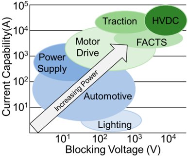
- Paralleling is necessary for high-current applications; a single Si-IGBT chip for 1200/1700 V is limited to approximately 200 A, motivating parallel chips, discrete devices, half-bridges/arms/legs, or modules.
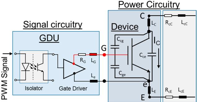
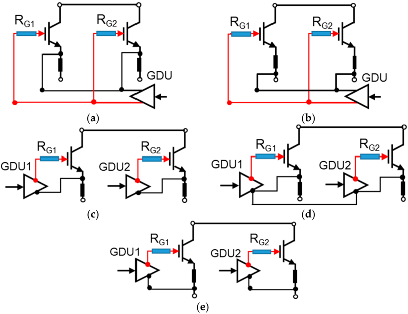
- Current imbalance is categorized as static and dynamic. Static unbalancing is affected by on-state voltage/on-state resistance, gate-emitter voltage, junction temperature, and total loop resistance; dynamic unbalancing is affected by threshold voltage, gate signal propagation delay, rise/fall times, gate resistance, parasitic capacitances, power loop inductance, and gate loop inductance.
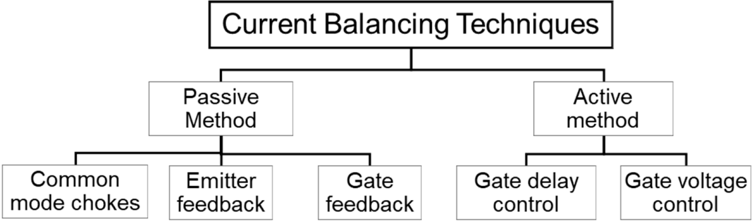
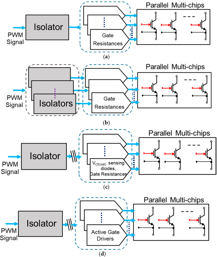
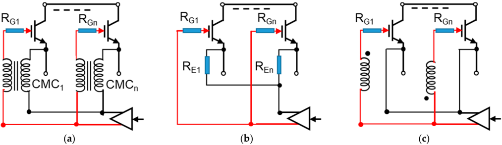
- Passive techniques—device matching, symmetric layout, common mode chokes, emitter feedback, and differential choke-based gate feedback—can improve or minimize imbalance but generally cannot realize optimized current sharing. Active gate control—gate delay control, gate voltage control, and dynamic gate resistance—can provide improved/optimized sharing but faces implementation complexity and cost.
- Reliability concerns include current imbalance up to 50% due to turn-off delay and turn-off voltage slope during turn-off, requiring turn-off current reduction by 50% to stay within SOA; thermal stability requires \((\partial P_G/\partial T) \le (\partial P_D/\partial T)\).
Methods
- Design: review and analysis of paralleling issues for IGBT power semiconductor devices, including device physics, system parameters, gate-driving topologies, and current-balancing techniques.
- Data/sample: no original experimental sample is reported; the paper synthesizes prior studies, manufacturer application notes, and referenced literature.
- Main analysis: categorizes static vs. dynamic current unbalancing, passive vs. active gate-driving/current-balancing methods, and summarizes system parameters and passive method performance in Table 1 and Table 2.
Limitations
- The paper states no explicit limitations section.
- Evident from the text: it is a review/synthesis without new experimental validation or original measurements.
- Evident from the text: some cited studies lack quantitative detail—for example, differences in unequal \(L_E\) and \(L_C\) are “not mentioned quantitatively” in reference [8].
Model-written summary. Check it against the paper before relying on it.
Integrity signals
Registry
Cites
Statistics
Figures
Verification
Claims the paper makes
42 Own interpretation · 41 No full text of the sources · 31 Not checked yet · 3 No basis given
In the paper
“One conventional approach to achieving the operating criterion considering thermal stability and the SOA limit is derating the chips/power modules [16].”
§ Paralleling of IGBT Power Semiconductor Devices and Reliability Issues > 3. Gate-Driving Techniques
What the sources say
- Not checked — no full text of the sourcecites [16] Schlapbach, U. (2010, January 16–18). Dynamic paralleling problems in IGBT module construction and application. Proceedings of the International Conference on Integrated Power Electronics Systems, Nuremberg, Germany.
plainstates a cause- Asserted: passes — The authors put it forward as true.
- Checkable: passes — It can be checked against evidence.
- Load-bearing: unclear — It is unclear whether the paper’s conclusions depend on it.
- Based: passes — The paper gives a reason why it holds.
A claim is checked only against the cited paper’s full text, never its abstract, and none is available for its sources.
In the paper
“Furthermore, applications of the medium voltage class, i.e., 3.3 kV, 4.5 kV, and 6.5 kV, for high-power industrial drives, have similar current limitation constraints [7][8][9].”
§ Paralleling of IGBT Power Semiconductor Devices and Reliability Issues > 1. Introduction
What the sources say
- Not checked — no full text of the sourcecites [7] Chen, 2014, Dynamic Characterization of Parallel-Connected High-Power IGBT Modules, IEEE Trans. Ind. Appl. source
- Not checked — no full text of the sourcecites [8] Werner, R., Weigel, J., Boehmer, J., and Eckel, H.-G. (2019, January 7–9). Potential of passive feedbacks to reduce dynamic current imbalances of paralleled IGBTs. Proceedings of the PCIM Europe International Exhibition and Conference for Power Electronics, Intelligent Motion, Renewable Energy and Energy Management, Nuremberg, Germany. source
- Not checked — no full text of the sourcecites [9] Jadhav, V., Zhou, Y., and Jansen, U. (2016, January 28–30). Analysis of different IGBT gate driver strategies influencing dynamic paralleling performance. Proceedings of the PCIM Asia International Exhibition and Conference for Power Electronics, Intelligent Motion, Renewable Energy and Energy Management, Shanghai, China.
plain- Asserted: passes — The authors put it forward as true.
- Checkable: passes — It can be checked against evidence.
- Load-bearing: unclear — It is unclear whether the paper’s conclusions depend on it.
- Based: passes — The paper gives a reason why it holds.
In the paper
“The gate-driving layout determines the gate current path, and an asymmetric gatedriving layout results in parallel-connected power devices due to the asymmetric gate current path [9].”
§ Paralleling of IGBT Power Semiconductor Devices and Reliability Issues > 2.2. Gate-Driving Parameters
What the sources say
- Not checked — no full text of the sourcecites [9] Jadhav, V., Zhou, Y., and Jansen, U. (2016, January 28–30). Analysis of different IGBT gate driver strategies influencing dynamic paralleling performance. Proceedings of the PCIM Asia International Exhibition and Conference for Power Electronics, Intelligent Motion, Renewable Energy and Energy Management, Shanghai, China.
plainstates a cause- Asserted: passes — The authors put it forward as true.
- Checkable: passes — It can be checked against evidence.
- Load-bearing: unclear — It is unclear whether the paper’s conclusions depend on it.
- Based: passes — The paper gives a reason why it holds.
A statement the paper makes itself — it cites no source for it, so there is none to check. The quote shows it is in the paper.
In the paper
“Device matching: Ensuring close matching of device parameters, such as Rds,on and VG,th, helps promote current sharing among parallel devices.”
§ Paralleling of IGBT Power Semiconductor Devices and Reliability Issues > 1. Introduction
plainstates a cause- Asserted: passes — The authors put it forward as true.
- Checkable: passes — It can be checked against evidence.
- Load-bearing: passes — The paper’s conclusions depend on it.
- Based: passes — The paper gives a reason why it holds.
In the paper
“The emitter feedback provides improved dynamic current sharing with an asymmetric gate drive length, as well as an asymmetric busbar configuration.”
§ Paralleling of IGBT Power Semiconductor Devices and Reliability Issues > 3.2.2. Emitter Feedback
What the sources say
- Not checked — no full text of the sourcecites [9] Jadhav, V., Zhou, Y., and Jansen, U. (2016, January 28–30). Analysis of different IGBT gate driver strategies influencing dynamic paralleling performance. Proceedings of the PCIM Asia International Exhibition and Conference for Power Electronics, Intelligent Motion, Renewable Energy and Energy Management, Shanghai, China.
plainstates a cause- Asserted: passes — The authors put it forward as true.
- Checkable: passes — It can be checked against evidence.
- Load-bearing: passes — The paper’s conclusions depend on it.
- Based: passes — The paper gives a reason why it holds.
48 more claims
Create a free account to see all 117 claims and to verify the 35 references still open.
- Probably not a substantial claim. 30
- It may state two separate claims as one. 41
Self-check
Percentages, sums and reported differences re-computed from the paper’s own numbers.
Each contradiction between two passages listed here was confirmed by an independent check.
Rated minor: it would not touch a result — a value no result rests on, a p-value that stays on the same side of the significance level, or a conflict that is clerical, resolved elsewhere in the paper, or outside its own findings.
In the paper
§ Paralleling of IGBT Power Semiconductor Devices and Reliability Issues > 3.3. Active Gate-Driving Control Techniques
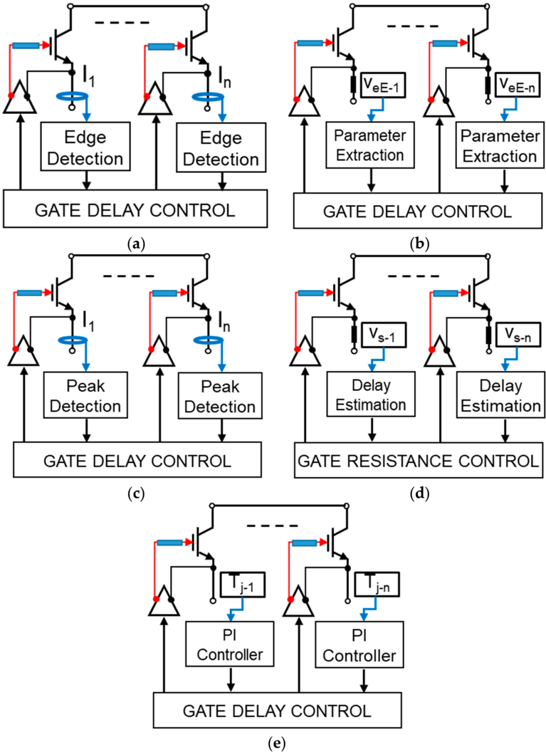
“The active gate control methods are summarized in Figure 8 using a schematic representation of the techniques.”
§ Paralleling of IGBT Power Semiconductor Devices and Reliability Issues > 4.3. Reliability, Derating, and Stability Factors
“Figure 8. Schematic diagram of passive gate-driving technique for parallel-connected power devices: (a) common mode chokes; (b) emitter feedback through common auxiliary emitter; and (c) gate current feedback using differential mode chokes.”
Rated minor: it would not touch a result — a value no result rests on, a p-value that stays on the same side of the significance level, or a conflict that is clerical, resolved elsewhere in the paper, or outside its own findings.
In the paper
§ Paralleling of IGBT Power Semiconductor Devices and Reliability Issues > 1. Introduction
“The static and dynamic behavior of paralleled IGBTs was discussed in [17] in 1990.”
§ Paralleling of IGBT Power Semiconductor Devices and Reliability Issues > References
“17. Letor, R. Static and dynamic behaviour of paralleled IGBTs. IEEE Trans. Ind. Appl. 1992, 28, 359-402.”
Rated minor: it would not touch a result — a value no result rests on, a p-value that stays on the same side of the significance level, or a conflict that is clerical, resolved elsewhere in the paper, or outside its own findings.
In the paper
§ Paralleling of IGBT Power Semiconductor Devices and Reliability Issues > 4.1. Influence of Parameters and Passive Gate Control
“turn-off energy (∆E off ) with the collector-emitter voltage (∆V CE,sat ) and turn-off delay time (∆t dvoff )”
§ Paralleling of IGBT Power Semiconductor Devices and Reliability Issues > 4.1. Influence of Parameters and Passive Gate Control
“∆E on = f ∆V CE , ∆t dvo f f”
Citations
Cites
Bortis, D., Biela, J., & Kolar, J. W. (2008) · IEEE Transactions on Plasma Science · doi:10.1109/tps.2008.2003971 · Cited by 127
Li, H., Zhou, W. J., Wang, X., Munk‐Nielsen, S., Li, D., Wang, Y., & Dai, X. (2018) · IEEE Transactions on Power Electronics · doi:10.1109/tpel.2018.2797326 · Cited by 106
Review of series and parallel connection of IGBTs
Shammas, N. Y. A., Withanage, R., & Chamund, D. (2006) · IEE Proceedings - Circuits, Devices and Systems · doi:10.1049/ip-cds:20050053 · Cited by 94
Static and dynamic behavior of paralleled IGBTs
Letor, R. (1992) · IEEE Transactions on Industry Applications · doi:10.1109/28.126748 · Cited by 86
Dynamic Characterization of Parallel-Connected High-Power IGBT Modules
Chen, N., Chimento, F., Nawaz, M., & Wang, L. (2015) · IEEE Transactions on Industry Applications · doi:10.1109/tia.2014.2330075 · Cited by 65
Dynamic gate resistance control for current balancing in parallel connected IGBTs
Sasaki, M., Nishio, H., & Ng, W. T. (2013) · 2013 Twenty-Eighth Annual IEEE Applied Power Electronics Conference and Exposition (APEC) · doi:10.1109/apec.2013.6520216 · Cited by 53
Wu, R., Smirnova, L., Wang, H., Iannuzzo, F., & Blaabjerg, F. (2015) · 2015 9th International Conference on Power Electronics and ECCE Asia (ICPE-ECCE Asia) · doi:10.1109/icpe.2015.7167881 · Cited by 47
Paralleling intelligent IGBT power modules with active gate-controlled current balancing
Hofer, P., Karrer, N., & Gerster, C. (2002) · PESC Record. 27th Annual IEEE Power Electronics Specialists Conference · doi:10.1109/pesc.1996.548751 · Cited by 38
Role of Simulation Technology for the Progress in Power Devices and Their Applications
Ohashi, H., & Omura, I. (2013) · IEEE Transactions on Electron Devices · doi:10.1109/ted.2012.2228272 · Cited by 36
Self-citationA new delay time compensation principle for parallel connected IGBTs
Alvarez, R., & Bernet, S. (2011) · 2011 IEEE Energy Conversion Congress and Exposition · doi:10.1109/ecce.2011.6064173 · Cited by 36
Investigation of parallel operation of IGBTs
Nelson, J. J., Venkataramanan, G., & Beihoff, B. C. (2003) · Conference Record of the 2002 IEEE Industry Applications Conference. 37th IAS Annual Meeting (Cat. No.02CH37344) · doi:10.1109/ias.2002.1042811 · Cited by 30
Current sharing of IGBT modules in parallel with thermal imbalance
Wang, X., Zhao, Z., & Yuan, L. (2010) · 2010 IEEE Energy Conversion Congress and Exposition · doi:10.1109/ecce.2010.5618253 · Cited by 26
Decentralized active gate control for current balancing of parallel connected IGBT modules
Lobsiger, Y., Bortis, D., & Kolar, J. W. (2011) · European Conference on Power Electronics and Applications · Cited by 25
Sasaki, M., Nishio, H., Shorten, A., & Ng, W. T. (2013) · 2013 25th International Symposium on Power Semiconductor Devices & IC's (ISPSD) · doi:10.1109/ispsd.2013.6694398 · Cited by 24
Performance of Parallel Connected SiC MOSFETs under Short Circuits Conditions
Wu, R., Mendy, S., Agbo, N., Gonzalez, J., Jahdi, S., & Alatise, O. (2021) · Energies · doi:10.3390/en14206834 · Cited by 21
Sinusoidal Current Operation of Delay-Time Compensation for Parallel-Connected IGBTs
Alvarez, R., & Bernet, S. (2014) · IEEE Transactions on Industry Applications · doi:10.1109/tia.2014.2305905 · Cited by 19
Wide Band-Gap Semiconductor Based Power Electronics for Energy Efficiency
Kizilyalli, I. C., Carlson, E. P., Cunningham, D. W., Manser, J. S., Xu, Y. A., & Liu, A. Y. (2018) · doi:10.2172/1464211 · Cited by 17
Simulation and experimental investigation of parallel connected IGBTs
Alvarez, R., Fink, K., & Bernet, S. (2010) · 2010 IEEE International Conference on Industrial Technology · doi:10.1109/icit.2010.5472617 · Cited by 16
Current sharing model of parallel connected IGBTs during turn-on
Xiao, Y., Liu, Q., Tang, Y., Du, L., & Ma, H. (2014) · Annual Conference of the IEEE Industrial Electronics Society (IECON) · doi:10.1109/iecon.2014.7048677 · Cited by 14
Weigel, J., Boehmer, J., Nagel, A., & Kleffel, R. (2017) · 2017 19th European Conference on Power Electronics and Applications (EPE'17 ECCE Europe) · doi:10.23919/epe17ecceeurope.2017.8099203 · Cited by 14
Peak minimisation-based gate delay compensation for active current balancing of parallel IGBT system
Tripathi, R. N., Tsukuda, M., & Omura, I. (2019) · Microelectronics Reliability · doi:10.1016/j.microrel.2019.113426 · Cited by 13
Self-citationRahimi, T., Ding, L., Abadifard, A., Ghavidel, P., Farhadi, M., & Faraji, R. (2021) · Case Studies in Thermal Engineering · doi:10.1016/j.csite.2021.101134 · Cited by 13
Current sharing control strategy for IGBTs connected in Parallel
Perez-Delgado, R., Velasco-Quesada, G., & Roman-Lumbreras, M. (2016) · Journal of Power Electronics · doi:10.6113/jpe.2016.16.2.769 · Cited by 12
Parallel operation of high power IGBTs
Medaule, D. (1995) · IEE Colloquium on `IGBT Propulsion Drives' · doi:10.1049/ic:19950529 · Cited by 10
Current mismatch during switching due to the self-turn-off effect in paralleled IGBT
Böhmer, J. R., Schümann, J., Fleisch, K., & Eckel, H.-G. (2013) · European Conference on Power Electronics and Applications · doi:10.1109/epe.2013.6631771 · Cited by 9
Brandelero, J., Ewanchuk, J., Degrenne, N., & Mollov, S. (2018) · Microelectronics Reliability · doi:10.1016/j.microrel.2018.07.034 · Cited by 9
Tripathi, R. N., Tsukuda, M., & Omura, I. (2018) · Microelectronics Reliability · doi:10.1016/j.microrel.2018.06.030 · Cited by 4
Self-citationMutual influence of quasistatic and dynamic current imbalances of paralleled IGBTs
Werner, R., da Cunha, J., & Eckel, H.-G. (2019) · 2019 21st European Conference on Power Electronics and Applications (EPE '19 ECCE Europe) · doi:10.23919/epe.2019.8915438 · Cited by 4
Kono, H., & Omura, I. (2022) · IEEE Transactions on Electron Devices · doi:10.1109/ted.2022.3202883 · Cited by 2
Self-citation(2010) · International Conference on Integrated Power Electronics Systems (CIPS)
(2016)
(2020)
Self-citation
Research works printed but not linked: 7
- Schrader, R., Muenster, P., and Eckel, H.-G. (2018, January 5–7). Dynamic Current Sharing and Gate Feedback During Turn-OFF of Paralleled IGBTs. Proceedings of the PCIM Europe Europe International Exhibition and Conference for Power Electronics, Intelligent Motion, Renewable Energy and Energy Management, Nuremberg, Germany.
- Wintrich, A., Nascimento, J., Leipenat, M., Gmbh, S.E., and Kg, C. (June, January 30). Influence of parameter distribution and mechanical construction on switching behaviour of parallel IGBT. Proceedings of the PCIM Europe International Conference Power Electronics, Intelligent Motion, Power Quality, Nuremberg, Germany.
- Joyce, J. (2001). Current Sharing and Redistribution in High Power IGBT Modules. [Ph.D. Thesis, University of Cambridge].
- Yong, T., Bo, W., and Jie, L.Q. (2019, January 21–23). Research on Parallel Operation Characteristic and current sharing method of High Power IGBT. Proceedings of the Journal of Physics: Conference Series, Joint 2019 International Conference on Ubiquitous Power Internet of Things (UPIOT 2019) & 2019 3rd International Symposium on Green Energy and Smart Grid (SGESG 2019), Chongqing, China.
- Schrader, R., Cordt, D., Münster, P., and Eckel, H.-G. (2018, January 17–21). Influences of gate-circuit and parasitic inductances on turn-OFF current imbalances of paralleled IGBTs due to differences in their switching behavior. Proceedings of the European Conference on Power Electronics and Applications (EPE ECCE Europe), Riga, Latvia.
- Chamund, D., Findlay, B., Birkett, K., and Shammas, N. (2002, January 9–11). Parallel operation of IGBT modules using de-rating factors’. Proceedings of the 37th International Universities Power Engineering Conference (UPEC), Stafford, UK.
- Chen, J.-F., Lin, J.-N., and Ai, T.-H. (1996, January 5–10). The Techniques of the Serial and Paralleled IGBTs. IEEE IECON. Proceedings of the 22nd International Conference on Industrial Electronics, Control, and Instrumentation, Taipei, Taiwan.
Cited by
Energy management control strategies for energy storage systems of hybrid electric vehicle: A review
Veerendra, A. S., Mohamed, M. R., & Márquez, F. P. G. (2024) · Energy Storage · doi:10.1002/est2.573 · Cited by 69
Study on dislocation propagation in 300-mm Si wafer during a high thermal budget process
Yuan, J., Cai, B., Miyamura, Y., Saito, W., & Nishizawa, S. (2025) · Materials Science in Semiconductor Processing · doi:10.1016/j.mssp.2025.109977 · Cited by 4
Li, C., Liu, B., Zhu, Q., Yu, Q., Cao, J., Du, Y., Jain, P., & Song, G. (2024) · IEEE International Conference on Power Science and Technology (ICPST) · doi:10.1109/icpst61417.2024.10601737 · Cited by 2
Current imbalance analysis of multichip influenced by parasitic inductance within PP-IEGT
Wang, Z., Dai, S., Zhao, Y., Li, G., Ji, B., Pickert, V., Gu, B., & Ding, S. (2023) · Microelectronics Reliability · doi:10.1016/j.microrel.2023.115275 · Cited by 1
Liu, Y., Zhu, Q., Liu, B., Du, Y., Cao, J., Jain, P., Song, G., Li, C., Dou, Z., & Yu, Q. (2024) · International Power Electronics and Motion Control Conference (EPE-PEMC) · doi:10.1109/ipemc-ecceasia60879.2024.10567778 · Cited by 1
Metadata
- Authors
- Tripathi, R. N., & Omura, I.
- Affiliations
- Kyushu Institute of Technology (JP)
- Corresponding author
- Tripathi, Ravi Nath
- ORCID
- Tripathi, Ravi Nath
- Venue
- Electronics
- Publisher
- MDPI AG
- Published
- 2023-09-10
- Volume
- 12
- Issue
- 18
- Pages
- 3826
- ISSN
- 2079-9292 (ISSN-L)
- OpenAlex
- W4386601598
- Semantic Scholar
- 3488f2ff2d684ac119add22dc7ede46b64e4abfb
- Cited by
- 14
- References
- 33
- Citations by year
- 2026: 5 · 2025: 5 · 2024: 3 · 2023: 1
- FWCI
- 1.00
- Type
- journal article
- Language
- en
- Open access
- gold
- doi.org
- Licence
- Locations
- Electronics (publishedVersion, cc-by)
- Institutional Repositories DataBase (IRDB) (publishedVersion, cc-by)
- Funders
- Japan Society for the Promotion of Science (JSPS) KAKENHI (20K14720.N)
- Topics
- Physical Sciences › Engineering › Electrical and Electronic Engineering › Silicon Carbide Semiconductor Technologies
- Physical Sciences › Engineering › Electrical and Electronic Engineering › Multilevel Inverters and Converters
- Physical Sciences › Engineering › Electrical and Electronic Engineering › Electric Power Systems and Control
- Keywords
- IGBT, power semiconductor devices, reliability, current sharing, aging materials, derating
About these checks
Registry, retraction, Cites and statistics results are computed, not judged, with one exception: a printed reference that no index lists is read once by a model before it counts as a citation error. Claims are extracted by a model and kept only when their quote appears verbatim in the text; each cited source is then checked, with a model’s help, for whether it says what the claim relies on. Those verdicts can be wrong — read the claim’s quote and the cited source before relying on one.
A language model drew the claims from the paper on 2026-11-12, under version 3 of the claim definition (model deepseek-v4.1-flash, prompt extract-v3).
A second model labelled each claim on 2026-11-12 (model jev-1.13-20260917, definition revision gold-guideline-v0.2).
Statistics and arithmetic are recomputed, not judged.
Confidence bands are shown only for fields calibrated on our annotated test set. None is calibrated yet, so no band is shown.
What counts as a claim ›How we measure confidence ›How we check this ›
Are you an author, or do you see a problem with this page? Request a review
Data sources
Bibliographic data: Semantic Scholar, OpenAlex, Crossref.
Contains information from the Semantic Scholar Academic Graph Datasets, made available under the ODC Attribution License (ODC-BY 1.0).
Semantic Scholar’s data is described in: Kinney, R., et al. (2023). The Semantic Scholar Open Data Platform. arXiv:2301.10140.
