

Plasma propulsion modeling with particle-based algorithms
Open accessThe DOI matches its Crossref record; 344 of the 344 references it cites were found in a registry or an index; 78 of the 190 sources its claims cite were checked for support.
Abstract
Perspective overview of PIC/MCC models for plasma propulsion and recent computational progress including plasma chemistry Monte Carlo modules for molecular and alternative propellants.
Overview
CoChat Summary
TL;DR
This perspective paper reviews particle-in-cell/Monte Carlo collision modeling of electric propulsion, covering electrostatic and electromagnetic thrusters, plasma plumes, plasma-wall interaction, and computational acceleration methods. It argues that particle-based models are essential for kinetic, non-local thruster physics but remain limited by computational cost, input-data gaps, and simplified electron/plume treatments.
Key findings
- PIC/Monte Carlo models are presented as the main kinetic tool for low-pressure, partially magnetized electric-thruster plasmas, with ES thrusters requiring Poisson’s equation and EM thrusters requiring a larger set of Maxwell’s equations.
- Computational demands are severe: for pulsed arc thrusters, plasma density peaks at \(10^{22}\ \mathrm{m^{-3}}\), giving \(\lambda_{D,e}\approx O(10^{-7})\ \mathrm{m}\) and \(\Delta t\approx O(10^{-13})\ \mathrm{s}\), requiring about \(10^8\) time steps for a few \(\mu\)s; other ES thrusters typically reach \(10^{18}\ \mathrm{m^{-3}}\), \(\lambda_{D,e}\approx O(10^{-5})\ \mathrm{m}\), \(\Delta t\approx O(10^{-11})\ \mathrm{s}\), and about \(10^7\) time steps.
- New numerical methods report large gains: sparse-grid ES PIC achieved a computational-time gain of 6.5 for the same resources in a Hall-thruster ECDI case; reduced-dimensional-order PIC showed speed-ups up to 50 versus 2D and an expected quasi-3D speed-up of about 2500 versus full 3D.
- Plasma-wall and plume studies highlight important effects: ion flux to unshielded walls can be up to 40% of total ion production; including non-neutral regions near a spacecraft increased ion backflow current by approximately 20%; reversed propellant injection increased utilization efficiency by a maximum of 30%; one ECR magnetic-field shape increased extraction efficiency by 50%.
Methods
- Design: a perspective/review article, not a primary experimental or numerical study; it synthesizes particle-based modeling approaches for plasma propulsion.
- Data/sample: literature and prior simulation/experimental studies across ES devices (E×B, pulsed arc, electrospray, gridded ion engines) and EM devices (RF inductive, helicon, ECR, MPDT), plus plume and spacecraft-interaction models.
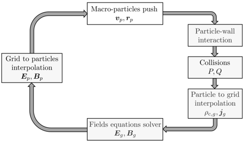
- Analysis: narrative overview of PIC/MCC algorithms, plasma-wall interaction models, hybrid versus full-PIC plume approaches, HPC techniques, and emerging methods such as sparse grids, implicit/energy-conserving PIC, reduced-order PIC, and deep-learning-based PIC.
Limitations
- The paper states that explicit PIC is constrained by Debye-length, plasma-period, and CFL restrictions, making multidimensional high-density simulations computationally expensive; numerical tricks such as enlarged permittivity or mass/size scaling are still used.
- It states that hybrid plume models with polytropic or Boltzmann electrons miss kinetic electron cooling, anisotropy, and peripheral/backflow plasma behavior, and that low-energy data for secondary electron emission, sputtering, neutral reflection, and ion recombination are lacking.
- Evident from the text: as a perspective/review, it presents no new primary data, no single validation study, and its forward-looking claims about future methods are authors’ assessments rather than demonstrated results.
Model-written summary. Check it against the paper before relying on it.
Integrity signals
Registry
Cites
Statistics
Figures

Verification
Claims the paper makes
14 Valid · 44 Not valid · 34 Not checked · 63 Own results and interpretations
Some cited sources support this claim and some don’t — read each source’s verdict below.
In the paper
“Therefore, such discharges are often modeled either by the two-fluid 109-112 or by hybrid 21,27 (fluid for electrons and particle for ions, see Sec. IV A) descriptions.”
What the sources say
- Could not verifycites [109] 2023, Two-dimensional effects on electrostatic instabilities in Hall thrusters. I. Insights from particle-in-cell simulations and two-point power spectral density reconstruction techniques, Phys. Plasmas sourceExperimental — accuracy not yet measured
The Introduction and Section II describe this paper’s PIC simulation of charged particles coupled to a fluid model for neutral gas. They do not address whether such discharges are often modeled with two-fluid descriptions or with the specified hybrid approach of fluid electrons and particle ions (searched: two-fluid, hybrid, fluid electrons/particle ions). (LLM, conf=0.72)
- Could not verifycites [110] 2017, 2D particle-in-cell simulations of the electron drift instability and associated anomalous electron transport in Hall-effect thrusters, Plasma Sources Sci. Technol. sourceExperimental — accuracy not yet measured
The citation is attached to the hybrid-description portion of the sentence. The Introduction and §2.2 describe particle-in-cell simulations, but the passages found for “hybrid,” “fluid,” and “two-fluid” do not address whether Hall-effect-thruster discharges are often modeled with hybrid fluid-electron/particle-ion descriptions. (LLM, conf=0.72)
- Disputedcites [111] 2019, Numerical studies of the E × B electron drift instability in Hall thrusters, Plasma Sources Sci. Technol. sourceExperimental — accuracy not yet measured
The citation is attached to the hybrid-model examples, but the source identifies its own approach as particle-in-cell/Monte Carlo collision (PIC-MCC), not a hybrid model with fluid electrons and particle ions. Section 3 (‘Two-dimensional PIC models’) states the method, and the Conclusions likewise describe two PIC-MCC models. No page numbers are available in our copy. (LLM, conf=0.87)
Checked by a reasoning model — may be wrong.
- Disputedcites [112] 2018, The effects of secondary electron emission on plasma sheath characteristics and electron transport in an discharge via kinetic simulations, Plasma Sources Sci. Technol. sourceExperimental — accuracy not yet measured
The citation is attached to the hybrid-description examples, but Section 2.1 identifies this paper’s model as a 2D-3V particle-in-cell/Monte-Carlo simulation, not a hybrid model with fluid electrons and particle ions. The Introduction mentions other fluid simulations; it does not describe this study as hybrid. (LLM, conf=0.86)
Checked by a reasoning model — may be wrong.
- Supportedcites [21] 2018, ID-HALL, a new double stage Hall thruster design. I. Principle and hybrid model of ID-HALL, Phys. Plasmas source
Section V describes simulations using a hybrid fluid-particle model. Section V.A specifies that it treats electrons as a fluid and ions as particles, supporting this paper as an example of the hybrid descriptions cited in the sentence. (LLM, conf=0.92)
- Supportedcites [27] 2021, Coupled plasma transport and electromagnetic wave simulation of an ECR thruster, Plasma Sources Sci. Technol. source
The Introduction describes this ECR-thruster discharge model as a hybrid PIC/fluid model. Sections 2.1 and 2.2 specify the division: ions are treated as particles and electrons as a fluid. The citation supports the hybrid example in the citing sentence; it is not offered as evidence for the separately cited two-fluid models. (LLM, conf=0.94)
plain- Asserted: passes — The authors put it forward as true.
- Checkable: passes — It can be checked against evidence.
- Load-bearing: passes — The paper’s conclusions depend on it.
- Based: passes — The paper gives a reason why it holds.
- Could not verify
The cited sources that could be checked couldn’t confirm or dispute this claim.
In the paper
“It has been recently 267,268 demonstrated that different numerical treatments of the neutrals change the spatio-temporal evolution of a HT discharge.”
What the sources say
- Could not verifycites [267] 2015, A collisionless plasma thruster plume expansion model, Plasma Sources Sci. Technol. sourceExperimental — accuracy not yet measured
The Abstract describes a collisionless model of far-region plume expansion, not the evolution of a Hall thruster discharge. The Introduction and section 5.3 discuss how neutrals affect plume collisions, but do not compare numerical treatments of neutrals or report their effects on spatio-temporal discharge evolution. Searches for those terms found no passage addressing the claim. (LLM, conf=0.75)
- Not checked — no full text of the sourcecites [268] 2015, Self-consistent model of a high-power Hall thruster plume, IEEE Trans. Plasma Sci. source
boostedstates a cause- Asserted: passes — The authors put it forward as true.
- Checkable: passes — It can be checked against evidence.
- Load-bearing: passes — The paper’s conclusions depend on it.
- Based: passes — The paper gives a reason why it holds.
- Could not verify
The cited sources that could be checked couldn’t confirm or dispute this claim.
In the paper
“Simulation results are highly sensitive to the model used for neutral dynamics.”
What the sources say
- Could not verifycites [267] 2015, A collisionless plasma thruster plume expansion model, Plasma Sources Sci. Technol. sourceExperimental — accuracy not yet measured
Section 5.1 reports that plume expansion differs appreciably with the assumed electron cooling rate, not with a model of neutral dynamics. Section 5.3 discusses neutrals and collisions but does not compare neutral-dynamics models or report that simulation results are highly sensitive to their choice. No page numbers are available in our copy. (LLM, conf=0.75)
- Not checked — no full text of the sourcecites [268] 2015, Self-consistent model of a high-power Hall thruster plume, IEEE Trans. Plasma Sci. source
boostedstates an association- Asserted: passes — The authors put it forward as true.
- Checkable: passes — It can be checked against evidence.
- Load-bearing: passes — The paper’s conclusions depend on it.
- Based: passes — The paper gives a reason why it holds.
- Could not verify
The cited sources that could be checked couldn’t confirm or dispute this claim.
In the paper
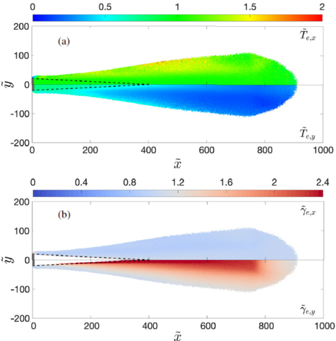
“Recent full PIC studies 243-245 , also observed a clear anisotropy in the electron parallel and perpendicular temperatures of a planar plume expansion.”
What the sources say
- Could not verifycites [243] 2020, Electron microphysics at plasma-solid interfaces, J. Appl. Phys. sourceExperimental — accuracy not yet measured
The Introduction (p. 1) and Synopsis (p. 16) discuss plasma–solid interfaces and their diagnostics, not planar plume expansion. Searches for the claimed electron-temperature anisotropy and full PIC studies found no passage in our copy addressing that observation. (LLM, conf=0.76)
- Not checked — no full text of the sourcecites [244] 2020, Plasma sheath material induced dependence due to secondary electron emission, Phys. Plasmas source
- Could not verifycites [245] 2013, Angular distribution of elastic electron backscattering from surfaces: Determination of the electron inelastic mean free path, J. Phys. D: Appl. Phys. sourceExperimental — accuracy not yet measured
The Results section describes Monte Carlo simulations of electrons elastically backscattered from solid surfaces, not full PIC studies of a planar plume. Searches for electron-temperature anisotropy and plume expansion found no passage addressing parallel and perpendicular electron temperatures. No page number was available in our copy. (LLM, conf=0.78)
boosted- Asserted: passes — The authors put it forward as true.
- Checkable: passes — It can be checked against evidence.
- Load-bearing: passes — The paper’s conclusions depend on it.
- Based: passes — The paper gives a reason why it holds.
- Could not verify
The cited sources support only part of this claim — read each source’s verdict below.
In the paper
“Moreover, the production of multiply charged ions from different species induced by the high-voltage [for example chlorine and carbon ions for polytetrafluoroethylene (PTFE) used as propellant for PPT 67 ] at very high densities leads to an obvious increase of the computational time, making it necessary to reduce the simulation cost with the usual numerical tricks cited above 66 .”
What the sources say
- Partly supportedcites [67] 2011, An energy- and charge-conserving, implicit, electrostatic particle-in-cell algorithm, J. Comput. Phys. sourceExperimental — accuracy not yet measured
Section 5.4 (pp. 20–23) supports the need to reduce PIC simulation costs: it explains how an implicit scheme can achieve CPU gains over an explicit one. It does not address the production of multiply charged ions from different species at very high densities or show that this production increases computational time. The chlorine and carbon ion example is attached to a different citation. (LLM, conf=0.86)
- Not checked — no full text of the sourcecites [66] 1999, Particle-in-cell plus direct simulation Monte Carlo (PIC-DSMC) approach for self-consistent plasma-gas simulations, IEEE Trans. Plasma Sci. source
boostedstates a cause- Asserted: passes — The authors put it forward as true.
- Checkable: passes — It can be checked against evidence.
- Load-bearing: unclear — It is unclear whether the paper’s conclusions depend on it.
- Based: passes — The paper gives a reason why it holds.
- Partly supported
57 more claims · 15 with their cited sources checked
Create a free account to see all 155 claims and to verify the 4 references still open.
- Probably not a substantial claim. 48
- It may state two separate claims as one. 67
- The quote only partly states this claim. 1
Citations
Cites
Items 201–344 of 344
Tondu, T., Belhaj, M., & Inguimbert, V. (2011) · Journal of Applied Physics · doi:10.1063/1.3653820 · Cited by 29
Pseudo-3D PIC modeling of drift-induced spatial inhomogeneities in planar magnetron plasmas
Revel, A., Minea, T. M., & Tsikata, S. (2016) · Physics of Plasmas · doi:10.1063/1.4964480 · Cited by 29
The effects of numerical acceleration techniques on PIC-MCC simulations of ion thrusters
Yuan, T., Ren, J., Zhou, J., Zhang, Z., Wang, Y., & Tang, H. (2020) · AIP Advances · doi:10.1063/1.5113561 · Cited by 29
Surface-driven asymmetry and instability in the acceleration region of Hall thruster
Taccogna, F., Longo, S., Capitelli, M., & Schneider, R. (2008) · Contributions to Plasma Physics · doi:10.1002/ctpp.200810061 · Cited by 28
Self-citationFar-Field Plume Characterization of a 100-W Class Hall Thruster
Hallouin, T., & Mazouffre, S. (2020) · Aerospace · doi:10.3390/aerospace7050058 · Cited by 28
Particle modeling of vacuum arc discharges
Yang, W., Sun, Q., & Zhou, Q. (2020) · Journal of Applied Physics · doi:10.1063/5.0014485 · Cited by 28
Numerical study of electron cyclotron drift instability: Application to Hall thruster
Asadi, Z., Taccogna, F., & Sharifian, M. (2019) · Frontiers in Physics · doi:10.3389/fphy.2019.00140 · Cited by 28
Self-citationDemonstration and experimental characteristics of a water-vapor Hall thruster
Shirasu, K., Kuwabara, H., Matsuura, M., Koizumi, H., Nakagawa, Y., Watanabe, H., Sekine, H., & Komurasaki, K. (2023) · Journal of Electric Propulsion · doi:10.1007/s44205-023-00047-w · Cited by 28
Eremin, D., Kemaneci, E., Matsukuma, M., Mussenbrock, T., & Brinkmann, R. P. (2023) · Plasma Sources Science and Technology · doi:10.1088/1361-6595/accecb · Cited by 27
Self-citationOn the limitations of hybrid particle-in-cell for ion thruster plume simulations
Wang, J., & Hu, Y. (2019) · Physics of Plasmas · doi:10.1063/1.5111791 · Cited by 27
Wen, D.-Q., Krek, J., Gudmundsson, J. T., Kawamura, E., Lieberman, M. A., & Verboncoeur, J. P. (2022) · IEEE Transactions on Plasma Science · doi:10.1109/tps.2022.3174401 · Cited by 27
Particle modelling of the hybrid negative ion source
Taccogna, F., Minelli, P., Diomede, P., Longo, S., Capitelli, M., & Schneider, R. (2011) · Plasma Sources Science and Technology · doi:10.1088/0963-0252/20/2/024009 · Cited by 27
Self-citationNumerical suite for cathodeless plasma thrusters
Magarotto, M., Fede, S. D., Souhair, N., Andrews, S., & Ponti, F. (2022) · Acta Astronautica · doi:10.1016/j.actaastro.2022.05.018 · Cited by 27
Computed versus measured ion velocity distribution functions in a Hall effect thruster
Garrigues, L., Mazouffre, S., & Bourgeois, G. (2012) · Journal of Applied Physics · doi:10.1063/1.4722269 · Cited by 27
Self-citationIon plume investigation of a Hall effect thruster operating with Xe/N 2 and Xe/air mixtures
Gurciullo, A., Fabris, A. L., & Cappelli, M. A. (2019) · Journal of Physics D: Applied Physics · doi:10.1088/1361-6463/ab36c5 · Cited by 26
Evaluation of angular scattering models for electron-neutral collisions in Monte Carlo simulations
Janssen, J. F. J., Pitchford, L. C., Hagelaar, G. J. M., & van Dijk, J. (2016) · Plasma Sources Science and Technology · doi:10.1088/0963-0252/25/5/055026 · Cited by 26
Yamashita, Y., Tani, Y., Tsukizaki, R., Koda, D., & Nishiyama, K. (2019) · Physics of Plasmas · doi:10.1063/1.5097661 · Cited by 26
Particle-in-cell simulations of Hall thruster acceleration and near plume regions
Katz, I., Chaplin, V. H., & Lopez Ortega, A. (2018) · Physics of Plasmas · doi:10.1063/1.5054009 · Cited by 26
Scaling laws for electrodeless plasma propulsion with water vapor propellant
Sheppard, A. J., & Little, J. M. (2020) · Plasma Sources Science and Technology · doi:10.1088/1361-6595/ab759e · Cited by 26
Numerical Analysis of a Miniature Microwave-discharge Ion Thruster Using Water as the Propellant
Nakamura, K., Nakagawa, Y., Koizumi, H., & Takao, Y. (2018) · TRANSACTIONS OF THE JAPAN SOCIETY FOR AERONAUTICAL AND SPACE SCIENCES · doi:10.2322/tjsass.61.152 · Cited by 26
Very-near-field plume simulation of a stationary plasma thruster
Taccogna, F., Longo, S., & Capitelli, M. (2004) · The European Physical Journal Applied Physics · doi:10.1051/epjap:2004151 · Cited by 26
Self-citationAxisymmetric Hybrid Plasma Model for Hall Effect Thrusters
Panelli, M., Morfei, D., Milo, B., D’Aniello, F. A., & Battista, F. (2021) · Particles · doi:10.3390/particles4020026 · Cited by 25
A Self-Consistent Open Boundary Condition for Fully Kinetic Plasma Thruster Plume Simulations
Jambunathan, R., & Levin, D. A. (2020) · IEEE Transactions on Plasma Science · doi:10.1109/tps.2020.2968887 · Cited by 25
High-performance computing and plasma physics
Dawson, J. M., Decyk, V., Sydora, R., & Liewer, P. (1993) · Physics Today · doi:10.1063/1.881386 · Cited by 24
Eremin, D., Engel, D., Krüger, D., Wilczek, S., Berger, B., Oberberg, M., Wölfel, C., Smolyakov, A., Lunze, J., Awakowicz, P., et al. (2023) · Plasma Sources Science and Technology · doi:10.1088/1361-6595/acc481 · Cited by 24
Self-citationThree-dimensional electromagnetic PIC model of a compact ECR plasma source
Gopinath, V. P., & Grotjohn, T. A. (1995) · IEEE Transactions on Plasma Science · doi:10.1109/27.467980 · Cited by 23
Gibson, A. R., Foucher, M., Marinov, D., et al. (2017) · Plasma Physics and Controlled Fusion · doi:10.1088/1361-6587/59/2/024004 · Cited by 23
Using electron fluid models to analyze plasma thruster discharges
Ahedo, E. (2023) · Journal of Electric Propulsion · doi:10.1007/s44205-022-00035-6 · Cited by 23
Sengupta, M., & Smolyakov, A. (2020) · Physics of Plasmas · doi:10.1063/1.5139035 · Cited by 23
Nakamura, K., Koizumi, H., Nakano, M., & Takao, Y. (2019) · Physics of Plasmas · doi:10.1063/1.5092754 · Cited by 23
Takase, K., Takahashi, K., & Takao, Y. (2018) · Physics of Plasmas · doi:10.1063/1.5015937 · Cited by 22
Parametric ion-acoustic turbulence in a helicon discharge
Virko, V. F., Kirichenko, G. S., & Shamrai, K. P. (2003) · Plasma Sources Science and Technology · doi:10.1088/0963-0252/12/2/313 · Cited by 22
Lapenta, G. (2023) · Physics · doi:10.3390/physics5010007 · Cited by 22
Eremin, D., Berger, B., Engel, D., Kallähn, J., Köhn, K., Krüger, D., Xu, L., Oberberg, M., Wölfel, C., Lunze, J., et al. (2023) · Plasma Sources Science and Technology · doi:10.1088/1361-6595/acc47f · Cited by 22
Self-citationThree-dimensional neutralizer effects on a Hall-effect thruster near plume
Cichocki, F., Domínguez-Vázquez, A., Merino, M., Fajardo, P., & Ahedo, E. (2021) · Acta Astronautica · doi:10.1016/j.actaastro.2021.06.042 · Cited by 21
Self-citationÁlvarez, R., & Alves, L. L. (2007) · Journal of Applied Physics · doi:10.1063/1.2732508 · Cited by 21
Three-dimensional plume simulation of multi-channel thruster configuration
Taccogna, F., Pagano, D., Scortecci, F., & Garulli, A. (2014) · Plasma Sources Science and Technology · doi:10.1088/0963-0252/23/6/065034 · Cited by 20
Self-citationA two-dimensional modelling study of a coaxial plasma waveguide
Rahimi, S., Jimenez-Diaz, M., Hübner, S. S., Kemaneci, E., van der Mullen, J. J. A. M., & van Dijk, J. (2014) · Journal of Physics D Applied Physics · doi:10.1088/0022-3727/47/12/125204 · Cited by 20
A data-driven approach for analyzing Hall thruster discharge instability leading to plasma blowoff
Lee, M., Kim, D.-H., Lee, J., Kim, Y., & Yi, M. (2023) · Acta Astronautica · doi:10.1016/j.actaastro.2023.02.017 · Cited by 20
Hiramoto, K., Nakagawa, Y., Koizumi, H., & Takao, Y. (2017) · Physics of Plasmas · doi:10.1063/1.4989734 · Cited by 20
Foundations of plasmas as ion sources
Jorns, B., & Lafleur, T. (2022) · Plasma Sources Science and Technology · doi:10.1088/1361-6595/aca560 · Cited by 20
Jablonski, A. (2014) · Journal of Physics D: Applied Physics · doi:10.1088/0022-3727/47/5/055301 · Cited by 19
Mattei, S., Nishida, K., Mochizuki, S., Grudiev, A., Lettry, J., Tran, M. Q., & Hatayama, A. (2016) · Plasma Sources Science and Technology · doi:10.1088/0963-0252/25/6/065001 · Cited by 19
Electromagnetic particle simulation of electron cyclotron resonance microwave discharge
Koh, W. H., Choi, N. H., Choi, D. I., & Oh, Y. H. (1993) · Journal of Applied Physics · doi:10.1063/1.352825 · Cited by 19
Andrews, S., Andriulli, R., Souhair, N., Fede, S. D., Pavarin, D., Ponti, F., & Magarotto, M. (2023) · Acta Astronautica · doi:10.1016/j.actaastro.2023.03.015 · Cited by 19
Berger, B., Eremin, D., Oberberg, M., Engel, D., Woelfel, C., Zhang, Q.-Z., Awakowicz, P., Lunze, J., Brinkmann, R. P., & Schulze, J. (2023) · Plasma Sources Science and Technology · doi:10.1088/1361-6595/acc480 · Cited by 19
Self-citationPETSc Users Manual (Revision 3.15)
Balay, S., Abhyankar, S. G., Adams, M. F., et al. (2021) · doi:10.2172/1814627 · Cited by 19
Sparse grid-based adaptive noise reduction strategy for particle-in-cell schemes
Muralikrishnan, S., Cerfon, A., Frey, M., et al. (2021) · Journal of Computational Physics X · doi:10.1016/j.jcpx.2021.100094 · Cited by 18
Magnetic Nozzle and RPA Simulations vs. Experiments for a Helicon Plasma Thruster Plume
Cichocki, F., Navarro-Cavallé, J., Modesti, A., & Vázquez, G. R. (2022) · Frontiers in Physics · doi:10.3389/fphy.2022.876684 · Cited by 18
Self-citationModeling grid erosion in the NEXT ion thruster using the CEX2D and CEX3D codes
Polk, J. E., Chaplin, V. H., Anderson, J. R., Yim, J., Soulas, G. C., Williams, G. J., III, & Shastry, R. (2023) · Journal of Electric Propulsion · doi:10.1007/s44205-023-00043-0 · Cited by 18
Azimuthal ion drift of a gridded ion thruster
Yamashita, Y., Tsukizaki, R., Yamamoto, Y., Koda, D., Nishiyama, K., & Kuninaka, H. (2018) · Plasma Sources Science and Technology · doi:10.1088/1361-6595/aae29b · Cited by 18
Practical analysis of different neutral algorithms for particle simulation of Hall thruster
Pan, R., Ren, J., Mao, R., & Tang, H. (2023) · Plasma Sources Science and Technology · doi:10.1088/1361-6595/acc134 · Cited by 18
Anisotropic electron heating in an electron cyclotron resonance thruster with magnetic nozzle
Porto, J., Elias, P.-Q., & Ciardi, A. (2023) · Physics of Plasmas · doi:10.1063/5.0124834 · Cited by 18
Mazières, V., Gaboriau, F., Guglielmi, A., Laquerbe, V., Pascaud, R., & Pascal, O. (2022) · Physics of Plasmas · doi:10.1063/5.0090774 · Cited by 17
Electron extraction mechanisms of a micro-ECR neutralizer
Takao, Y., Hiramoto, K., Nakagawa, Y., Kasagi, Y., Koizumi, H., & Komurasaki, K. (2016) · Japanese Journal of Applied Physics · doi:10.7567/jjap.55.07ld09 · Cited by 17
Kinetic modeling of E-to-H mode transition in inductively coupled hydrogen plasmas
Nishida, K., Mattei, S., Mochizuki, S., Lettry, J., & Hatayama, A. (2016) · Journal of Applied Physics · doi:10.1063/1.4953647 · Cited by 17
The role of noise in PIC and Vlasov simulations of the Buneman instability
Tavassoli, A., Chapurin, O., Jimenez, M., Zadeh, M. P., Zintel, T., Sengupta, M., Couëdel, L., Spiteri, R. J., Shoucri, M. M., & Smolyakov, A. I. (2021) · Physics of Plasmas · doi:10.1063/5.0070482 · Cited by 17
Numerical Study of Hall Thruster Plume and Sputtering Erosion
Li, Y., Wang, P., Yang-hua, O., et al. (2012) · Journal of Applied Mathematics · doi:10.1155/2012/327021 · Cited by 17
Faraji, F., Reza, M., & Knoll, A. K. (2023) · Journal of Applied Physics · doi:10.1063/5.0143292 · Cited by 17
Petronio, F., Charoy, T., Alvarez Laguna, A., Bourdon, A., & Chabert, P. (2023) · Physics of Plasmas · doi:10.1063/5.0119253 · Cited by 17
Problems of the theory of linear and nonlinear transformation of waves in inhomogeneous media
Erokhin, N. S., & Moiseev, S. S. (1973) · Soviet Physics Uspekhi · doi:10.1070/pu1973v016n01abeh005149 · Cited by 17
Parametric study of the radial plasma-wall interaction in a Hall thruster
Domínguez-Vázquez, A., Taccogna, F., Fajardo, P., & Ahedo, E. (2019) · Journal of Physics D: Applied Physics · doi:10.1088/1361-6463/ab3c7b · Cited by 17
Self-citationHall thruster microturbulence under conditions of modified electron wall emission
Tsikata, S., Héron, A., & Honoré, C. (2017) · Physics of Plasmas · doi:10.1063/1.4984255 · Cited by 16
Sparse grid reconstructions for Particle-In-Cell methods
Deluzet, F., Fubiani, G., Garrigues, L., et al. (2022) · ESAIM Mathematical Modelling and Numerical Analysis · doi:10.1051/m2an/2022055 · Cited by 16
Self-citationHow to build PIC-MCC models for Hall microthrusters
Minelli, P., & Taccogna, F. (2018) · IEEE Transactions on Plasma Science · doi:10.1109/tps.2017.2766182 · Cited by 16
Self-citationThe Development of CAM200 - Low Power Hall Thruster
Lev, D. R., Eytan, R., Alon, G., et al. (2016) · TRANSACTIONS OF THE JAPAN SOCIETY FOR AERONAUTICAL AND SPACE SCIENCES AEROSPACE TECHNOLOGY JAPAN · doi:10.2322/tastj.14.pb_217 · Cited by 16
Numerical investigation of internal plasma currents in a magnetic nozzle
Emoto, K., Takahashi, K., & Takao, Y. (2021) · Physics of Plasmas · doi:10.1063/5.0053336 · Cited by 16
Plasma ignition and steady state simulations of the Linac4 H− ion source
Mattei, S., Ohta, M., Yasumoto, M., Hatayama, A., Lettry, J., & Grudiev, A. (2013) · Review of Scientific Instruments · doi:10.1063/1.4833919 · Cited by 16
Chang, H.-Y., Alvarado, A., Weber, T., & Marian, J. (2019) · Nuclear Instruments and Methods in Physics Research Section B: Beam Interactions with Materials and Atoms · doi:10.1016/j.nimb.2019.05.079 · Cited by 15
Taccogna, F., Cichocki, F., & Minelli, P. (2022) · Frontiers in Physics · doi:10.3389/fphy.2022.1006994 · Cited by 15
Self-citationNonlinear effects and anomalous transport in RF plasmas
Chen, F. F. (2006) · IEEE Transactions on Plasma Science · doi:10.1109/tps.2006.874851 · Cited by 15
Data-driven analysis of oscillations in Hall thruster simulations
Maddaloni, D., Domínguez-Vázquez, A., Terragni, F., & Merino, M. (2022) · Plasma Sources Science and Technology · doi:10.1088/1361-6595/ac6444 · Cited by 15
Secondary electron emission yield in the limit of low electron energyPreprint
Andronov, A. N., Smirnov, A. S., Kaganovich, I., Startsev, E. A., Raitses, Y., & Demidov, V. I. (2013) · arXiv (Cornell University) · doi:10.48550/arxiv.1309.4658 · Cited by 15
Sato, Y., Koizumi, H., Nakano, M., & Takao, Y. (2019) · Journal of Applied Physics · doi:10.1063/1.5127805 · Cited by 14
Numerical investigation of internal plasma currents in a magnetic nozzle
Emoto, K., Takahashi, K., 80451491, Takao, Y., & 80552611 (2019) · Institutional Repositories DataBase (IRDB) · Cited by 14
ID-HALL, a new double stage Hall thruster design. I. Principle and hybrid model of ID-HALL
Dubois, L., Gaboriau, F., Liard, L., Harribey, D., Henaux, C., Garrigues, L., Hagelaar, G. J. H., Mazouffre, S., Boniface, C., & Boeuf, J. P. (2018) · Physics of Plasmas · doi:10.1063/1.5043354 · Cited by 14
Self-citationElectron microphysics at plasma-solid interfaces
Bronold, F. X., Rasek, K., & Fehske, H. (2020) · Journal of Applied Physics · doi:10.1063/5.0027406 · Cited by 14
Particle-in-cell simulation of the cathodic arc thruster
Lüskow, K. F., Neumann, P. R. C., Bandelow, G., Duras, J., Kahnfeld, D., Kemnitz, S., Matthias, P., Matyash, K., & Schneider, R. (2018) · Physics of Plasmas · doi:10.1063/1.5012584 · Cited by 14
Efficient parallelization for 3d-3v sparse grid Particle-In-Cell: Shared memory architectures
Deluzet, F., Fubiani, G., Garrigues, L., Guillet, C., & Narski, J. (2023) · Journal of Computational Physics · doi:10.1016/j.jcp.2023.112022 · Cited by 13
Self-citationYamashita, Y., Tsukizaki, R., & Nishiyama, K. (2022) · Journal of Electric Propulsion · doi:10.1007/s44205-022-00002-1 · Cited by 13
Simulations of ponderomotive effects in inductively coupled plasmas
Sydorenko, D., Smolyakov, A. I., Tyshetskiy, Y., & Godyak, V. A. (2005) · Physics of Plasmas · doi:10.1063/1.1849797 · Cited by 13
On the numerical dispersion of electromagnetic particle-in-cell code: Finite grid instability
Meyers, M. D., Huang, C.-K., Zeng, Y., Yi, S. A., & Albright, B. J. (2015) · Journal of Computational Physics · doi:10.1016/j.jcp.2015.05.037 · Cited by 13
Gibbons, M., & Hewett, D. W. (1997) · Journal of Computational Physics · doi:10.1006/jcph.1996.5475 · Cited by 13
Efficient parallelization for 3D-3V sparse grid Particle-In-Cell: Single GPU architectures
Deluzet, F., Fubiani, G., Garrigues, L., Guillet, C., & Narski, J. (2023) · Computer Physics Communications · doi:10.1016/j.cpc.2023.108755 · Cited by 13
Self-citationThree-dimensional geomagnetic field effects on a plasma thruster plume expansion
Cichocki, F., Merino, M., & Ahedo, E. (2020) · Acta Astronautica · doi:10.1016/j.actaastro.2020.05.019 · Cited by 13
Self-citationChaudhury, B., Shah, M. C., Parekh, U., Gandhi, H., Desai, P., Shah, K., Phadnis, A., Shah, M., Bandyopadhyay, M., & Chakraborty, A. K. (2019) · Communications in computer and information science · doi:10.1007/978-981-13-7729-7_3 · Cited by 13
Goebel, D. M., & Katz, I. M. (2008) · Wiley eBooks · doi:10.1002/9780470436448.ch7 · Cited by 13
PIC-DSMC Simulation of a Hall Thruster Plume with Charge Exchange Effects Using pdFOAM
Kang, S. H. (2023) · Aerospace · doi:10.3390/aerospace10010044 · Cited by 12
Fu, Y., Yang, J., Mou, H., Tan, R., Xia, X., & Gao, Z. (2022) · Computer Physics Communications · doi:10.1016/j.cpc.2022.108395 · Cited by 12
Numerical Investigation of Reversed Gas-Feed Configurations for Hall Thrusters
Boccelli, S., Magin, T., & Frezzotti, A. (2021) · Journal of Propulsion and Power · doi:10.2514/1.b38346 · Cited by 12
Enomoto, T., Parmar, S. M., Yamada, R., Wirz, R. E., & Takao, Y. (2022) · Journal of Electric Propulsion · doi:10.1007/s44205-022-00010-1 · Cited by 12
Simulation study on electron extraction mechanism of an ECR neutralizer
Fu, Y., Yang, J., Geng, H., Wu, X., Hu, Z., & Xia, X. (2021) · Vacuum · doi:10.1016/j.vacuum.2020.109932 · Cited by 11
Plasma sheath material induced dependence due to secondary electron emission
Pigeon, V., Claire, N., Arnas, C., Terasaka, K., & Inagaki, S. (2020) · Physics of Plasmas · doi:10.1063/1.5141348 · Cited by 11
Self-consistent particle modeling of inductively coupled CF/sub 4/ discharges and radical flow
Takekida, H., & Nanbu, K. (2006) · IEEE Transactions on Plasma Science · doi:10.1109/tps.2006.875730 · Cited by 11
Nonlinear electromagnetic fields in 0.5 MHz inductively coupled plasmas
Ostrikov, K., Tsakadze, E., Xu, S., Vladimirov, S. V., & Storer, R. (2003) · Physics of Plasmas · doi:10.1063/1.1557871 · Cited by 11
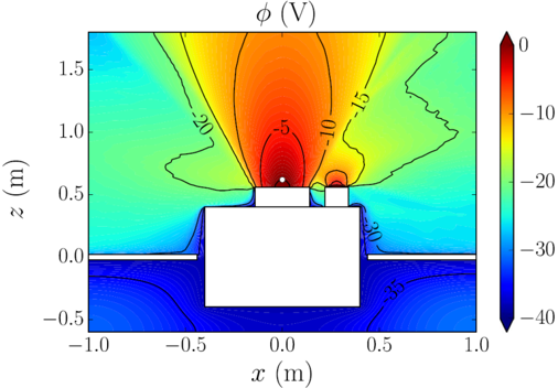
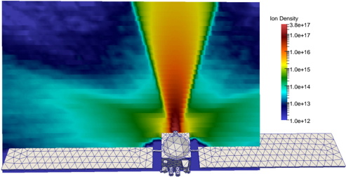
Multiscale coupling of spacecraft charging model with electric propulsion plume simulation
Araki, S. J. (2019) · IEEE Transactions on Plasma Science · doi:10.1109/tps.2019.2945534 · Cited by 10
On heavy particle-wall interaction in axisymmetric plasma discharges
Domínguez-Vázquez, A., Cichocki, F., Merino, M., Fajardo, P., & Ahedo, E. (2021) · Plasma Sources Science and Technology · doi:10.1088/1361-6595/ac1715 · Cited by 10
Self-citationAxial momentum gains of ions and electrons in magnetic nozzle acceleration
Emoto, K., Takahashi, K., & Takao, Y. (2021) · Plasma Sources Science and Technology · doi:10.1088/1361-6595/ac33ee · Cited by 10
Formation and neutralization of electric charge and current of an ion thruster plume
Perales-Díaz, J., Cichocki, F., Merino, M., & Ahedo, E. (2021) · Plasma Sources Science and Technology · doi:10.1088/1361-6595/ac2a19 · Cited by 10
Self-citationGarrigues, L., & Fubiani, G. (2023) · Journal of Applied Physics · doi:10.1063/5.0128759 · Cited by 10
Self-citationNon-local ponderomotive force in finite temperature inductive plasmas
Smolyakov, A. I., Sydorenko, D., & Froese, A. (2007) · Plasma Physics and Controlled Fusion · doi:10.1088/0741-3335/49/5a/s18 · Cited by 10
Analysis of Discharge Initiation in a RF Hydrogen Negative Ion Source
Hayami, T., Yoshinari, S., Terasaki, R., et al. (2011) · AIP conference proceedings · doi:10.1063/1.3637404 · Cited by 9
Macroscopic plasma analysis from 1D-radial kinetic results of a Hall thruster discharge
Marín-Cebrián, A., Domínguez-Vázquez, A., Fajardo, P., & Ahedo, E. (2021) · Plasma Sources Science and Technology · doi:10.1088/1361-6595/ac325e · Cited by 9
Liu, L., Cai, G., Zheng, H., Shang, S., & He, B. (2020) · Physics of Plasmas · doi:10.1063/5.0004874 · Cited by 9
Guerrero, P., Mikellides, I. G., Polk, J. E., Monreal, R., & Meiron, D. I. (2021) · Journal of Applied Physics · doi:10.1063/5.0055824 · Cited by 9
Equivalent two-dimensional numerical simulation of an ECR neutralizer
Fu, Y., Yang, J., Jin, Y., Xia, X., & Meng, H. (2019) · Acta Astronautica · doi:10.1016/j.actaastro.2019.07.018 · Cited by 9
Breathing modes in HEMP thrusters
Kahnfeld, D., Heidemann, R., Duras, J., Matthias, P., Bandelow, G., Lüskow, K., Kemnitz, S., Matyash, K., & Schneider, R. (2018) · Plasma Sources Science and Technology · doi:10.1088/1361-6595/aaf29a · Cited by 9
Binder, T., Pfeiffer, M., & Fasoulas, S. (2019) · AIP conference proceedings · doi:10.1063/1.5119534 · Cited by 8
Commentary: On helicon thrusters: Will they ever fly?
Takahashi, K., Charles, C., Boswell, R., et al. (2020) · Frontiers in Physics · doi:10.3389/fphy.2020.00277 · Cited by 8
A comprehensive analysis of electron emission from a-Si:H/Al 2 O 3 at low energies
Löffler, J., Belhaj, M., Bundaleski, N., Diaz Leon, J. J., Thomet, J., Frey, S., Ballif, C., & Wyrsch, N. (2023) · Journal of Physics D: Applied Physics · doi:10.1088/1361-6463/acaf37 · Cited by 8
Numerical aspects of particle-in-cell simulations for plasma-motion modeling of electric thrusters
Gallo, G., Isoldi, A., Del Gatto, D., Savino, R., Capozzoli, A., Curcio, C., & Liseno, A. (2021) · Aerospace · doi:10.3390/aerospace8050138 · Cited by 8
Particle Simulation Model for Self-Field Magnetoplasmadynamic Thruster
Li, J., Zhang, Y., Wu, J., Cheng, Y., & Du, X. (2019) · Energies · doi:10.3390/en12081579 · Cited by 7
BepiColombo: A Platform for Improving Modeling of Electric Propulsion-Spacecraft Interactions
Filleul, F., Sutherland, O., Cipriani, F., & Charles, C. (2021) · Frontiers in Space Technologies · doi:10.3389/frspt.2021.639819 · Cited by 7
Kinetic plasma dynamics in a radial model of a Hall thruster with a curved magnetic field
Marín-Cebrián, A., Domínguez-Vázquez, A., Fajardo, P., & Ahedo, E. (2022) · Plasma Sources Science and Technology · doi:10.1088/1361-6595/ac9a6b · Cited by 7
de Mejanes, N., Pascaud, R., Mazières, V., Rossi, A., Laquerbe, V., Garrigues, L., & Pascal, O. (2022) · Journal of Applied Physics · doi:10.1063/5.0095134 · Cited by 6
Self-citationPark, R. M., Kupets, W., Zammit, M. C., Colgan, J., Fontes, C. J., Scheiner, B. S., Timmermans, E., Tang, X.-Z., Scarlett, L. H., Fursa, D. V., et al. (2022) · Plasma Sources Science and Technology · doi:10.1088/1361-6595/ac781f · Cited by 6
Dynamic load balancing with over decomposition in plasma plume simulations
Araki, S. J., & Martin, R. (2022) · Journal of Parallel and Distributed Computing · doi:10.1016/j.jpdc.2022.01.023 · Cited by 6
Emoto, K., Takahashi, K., & Takao, Y. (2023) · Physics of Plasmas · doi:10.1063/5.0126901 · Cited by 6
Porto, J., & Elias, P.-Q. (2020) · IEEE Transactions on Antennas and Propagation · doi:10.1109/tap.2020.3044582 · Cited by 6
Wang, P., Borner, A., Li, Z., & Levin, D. A. (2013) · AIAA Plasmadynamics and Lasers Conference · doi:10.2514/6.2013-2629 · Cited by 6
(2005) · doi:10.1002/0471724254.ch4 · Cited by 6
Electric Propulsion Plume Simulation Coupled with Spacecraft Charging
Araki, S. J., & Barrie, A. C. (2018) · AIAA/ASME/SAE/ASEE Joint Propulsion Conference (JPC) · doi:10.2514/6.2018-4906 · Cited by 6
Particle distribution functions at plasma–surface interface
Costin, C. (2020) · AIP Advances · doi:10.1063/5.0030781 · Cited by 5
Sputtered atom transport calculation via Radiosity View Factor Model and particle data compression
Araki, S. J., & Martin, R. (2023) · Vacuum · doi:10.1016/j.vacuum.2023.111867 · Cited by 5
Incident angle dependence of reflected particles in low-energy xenon-ion impacts on metal surfaces
Ito, G., Kawashima, R., Komurasaki, K., & Koizumi, H. (2021) · Computational Materials Science · doi:10.1016/j.commatsci.2020.109989 · Cited by 4
Energy accommodation for gas ions on a polycrystalline material
Shuvalov, V. A. (1983) · Journal of Applied Mechanics and Technical Physics · doi:10.1007/bf00905614 · Cited by 4
Liu, Q., Yang, L., Huang, Y., Zhao, X., & Zheng, Z. (2019) · Plasma Science and Technology · doi:10.1088/2058-6272/aaff2e · Cited by 4
Jaafarian, R., Ganjovi, A. A., & Etaati, G. (2018) · Physics of Plasmas · doi:10.1063/1.5001753 · Cited by 3
Villemant, M., Belhaj, M., Sarrailh, P., Dadouch, S., Garrigues, L., & Boniface, C. (2019) · Europhysics Letters (EPL) · doi:10.1209/0295-5075/127/23001 · Cited by 3
Self-citationLifetime Simulation of an SPT-Type Hall Thruster by Using a 2D Fully Kinetic PIC Model
Cho, S., Komurasaki, K., & Arakawa, Y. (2012) · AIAA/ASME/SAE/ASEE Joint Propulsion Conference & Exhibit (JPC) · doi:10.2514/6.2012-4016 · Cited by 3
(2021) · Open Archive Toulouse Archive Ouverte (University of Toulouse) · Cited by 2
Some aspects of the plasma potential in 3D simulation of ECRIS operation
Li, L., Jin, X., Li, J., Li, L. X., & Li, B. (2022) · Physics of Plasmas · doi:10.1063/5.0097141 · Cited by 2
Simulation of plasmas for electric propulsion using the energy?conserving semi?implicit PIC scheme
Parodi, P., Magin, T., & Lapenta, G. (2022) · Lirias · doi:10.13009/eucass2022-7331 · Cited by 2
Mazières, V., Yung, T.-S., Herrero, L., Blanchet, A., Laquerbe, V., & Pascal, O. (2022) · Physics of Plasmas · doi:10.1063/5.0109311 · Cited by 2
Numerical Particle-In-Cell studies of Hall thrusters using unstructured grids
Villafana, W. (2026) · doi:10.70675/59d9e4e9zd34az4469z8038zfd399cdf2b38 · Cited by 2
Gueroult, R., Fubiani, G., & Garrigues, L. (2018) · Frontiers in Physics · doi:10.3389/fphy.2018.00128 · Cited by 1
Self-citationLaser-Induced Fluorescence Velocity Measurements of a Diverging Cusped Field Thruster
MacDonald, N. A., Cappelli, M. A., Gildea, S. R., et al. (2010) · doi:10.21236/ada533434
High-Density Helicon Plasma Science
Shinohara, S. (2022) · Springer Series in Plasma Science and Technology · doi:10.1007/978-981-19-2900-7
Erratum to “Gas–surface interactions and satellite drag coefficients”
Moe, K., & Moe, M. M. (2005) · Planetary and Space Science · doi:10.1016/j.pss.2005.10.002
Problems of the theory of linear and nonlinear transformation of waves in inhomogeneous media
Erokhin, N. S., & Moiseev, S. S. (1973) · Uspekhi Fizicheskih Nauk · doi:10.3367/ufnr.0109.197302a.0225
Parallel Particle-in-Cell Performance Optimization: A Case Study of Electrospray Simulation
Narayanan, R. K., & Madduri, K. (2017) · 2017 IEEE International Parallel and Distributed Processing Symposium Workshops (IPDPSW) · doi:10.1109/ipdpsw.2017.160
Solving unsymmetric sparse systems of linear equations with PARDISO
Schenk, O. (2003) · Future Generation Computer Systems · doi:10.1016/s0167-739x(03)00188-2
On helicon thrusters: Will they ever fly?
Godyak, V. (2020) · Journal of Applied Physics · doi:10.1063/1.5139998
Kornfeld, G., Koch, N., & Coustou, G. (n.d.) · 4th IEEE International Conference on Vacuum Electronics, 2003 · doi:10.1109/ivec.2003.1285973
Research works printed but not linked: 20
- 2005, Plasma Physics via Computer Simulation
- 2013, The DSMC Method
- 2021, Python Programming and Numerical Methods. A Guide for Engineers and Scientists
- 1988, Computer Simulation Using Particles
- 2010, Plasma Simulations by Example
- 2005, Computational Electrodynamics: The Finite-Difference Time-Domain Method
- 2007, Perfectly Matched Layer (PML) for Computational Electromagnetics
- 2018, Energy dissipation in helicon plasma at the near field of an antenna, Probl. At. Sci. Technol., 6, 86
- 2023, Density profile transition and high-energy electron transport in a magnetically expanding radio frequency plasma, Phys. Plasmas, 30, 013509, 10.1063/5.0126901 · DOI · Paper page
- 1957, On a singularity of the field of an electromagnetic wave propagated in an lnhomogeneous plasma, Sov. Phys. JETP, 4, 544
- 1996, Electron Cyclotron Resonance Ion Sources and ECR Plasmas
- D. Sydorenko , “Particle-in-cell simulations of electron dynamics in low pressure discharges with magnetic fields,” Ph.D. thesis (Department of Physics and Engineering Physics, University of Saskatchewan, 2006), unpublished thesis.
- 2006, Gaseous Electronics. Theory and Practice
- 2012, Gaseous Electronics. Tables, Atoms, and Molecules
- 2022, Programming Massively Parallel Processors: A Hands-on Approach
- 2014, Professional CUDA C Programming
- 2015, Heterogeneous Computing with OpenCL 2.0
- 2016, Parallel Programming with OpenACC
- 1981, A direct method for implicit particle-in-cell simulation, Commun. Plasma Phys. Control. Fusion, 6, 225
- 2021, GPU Porting of Scalable Implicit Solver with Green’s Function-Based Neural Networks by Openacc
Cited by
Faraji, F., & Reza, M. (2024) · Journal of Physics D Applied Physics · doi:10.1088/1361-6463/ada167 · Cited by 35
Digital twins for electric propulsion technologies
Reza, M., Faraji, F., & Knoll, A. K. (2024) · Journal of Electric Propulsion · doi:10.1007/s44205-024-00087-w · Cited by 18
“Because of the above complexities, the highest fidelity numerical approach most widely in use today, i.e., kinetic particle-in-cell (PIC) method, is prohibitively computationally costly to model full-size EP technologies over real-world operational timescales [34, 35].”
Reza, M., Faraji, F., & Knoll, A. K. (2024) · Plasma · doi:10.3390/plasma7030034 · Cited by 9
“The reduced-order PIC overall follows the standard algorithm of the particle-in-cell method [39–41].”
MethodPantera: A PIC-MCC-DSMC software for the simulation of rarefied gases and plasmas
Parodi, P., Boccelli, S., Bariselli, F., & Magin, T. (2025) · SoftwareX · doi:10.1016/j.softx.2025.102244 · Cited by 13
Data-driven local operator finding for reduced-order modeling of plasma systems
Faraji, F., Reza, M., Knoll, A. K., & Kutz, J. N. (2025) · Journal of Physics D Applied Physics · doi:10.1088/1361-6463/adbe85 · Cited by 8
“The positions and the velocities of the plasma particles are updated at each time step of the simulation according to the electromagnetic forces at the particles’ location [18, 19].”
Metadata
- Authors
- Taccogna, F., Cichocki, F., Eremin, D., Fubiani, G., & Garrigues, L.
- Affiliations
- Institute for the Science and Technology of Plasmas (IT)
- National Agency for New Technologies, Energy and Sustainable Economic Development (IT)
- Ruhr University Bochum (DE)
- Centre National de la Recherche Scientifique (FR)
- Venue
- Journal of Applied Physics
- Publisher
- AIP Publishing
- Published
- 2023-10-19
- Volume
- 134
- Issue
- 15
- ISSN
- 0021-8979 (ISSN-L)
- 1089-7550
- OpenAlex
- W4387781340
- Cited by
- 29
- References
- 327
- Citations by year
- 2026: 6 · 2025: 12 · 2024: 11
- FWCI
- 2.15
- Type
- journal article
- Language
- en
- Open access
- bronze
- doi.org
- Locations
- Journal of Applied Physics (publishedVersion)
- HAL (submittedVersion, other-oa)
- Funders
- Ministero dell'Università e della Ricerca (PON ARS01-00141)
- Agence Nationale de la Recherche (ANR) under the projet (ANR-22-CE46-0012)
- Topics
- Physical Sciences › Engineering › Electrical and Electronic Engineering › Low-Pressure Plasma Processing and Diagnostics
- Physical Sciences › Physics and Astronomy › Atomic and Molecular Physics, and Optics › Vacuum and Plasma Arcs
- Physical Sciences › Mathematics › Applied Mathematics › Gas Dynamics and Kinetic Theory
- Keywords
- plasma propulsion, particle-in-cell simulation, Monte Carlo collisions, electrostatic thrusters, electron cyclotron resonance thruster, plasma plume, plasma-wall interaction, plasma chemistry, alternative propellants
About these checks
Registry, retraction, Cites and statistics results are computed, not judged, with one exception: a printed reference that no index lists is read once by a model before it counts as a citation error. Claims are extracted by a model and kept only when their quote appears verbatim in the text; each cited source is then checked, with a model’s help, for whether it says what the claim relies on. Those verdicts can be wrong — read the claim’s quote and the cited source before relying on one.
The claim verdicts this report counts are experimental: their accuracy is not yet measured.
A language model drew the claims from the paper on 2026-10-12, under version 3 of the claim definition (model deepseek-v4.1-flash, prompt extract-v3).
A second model labelled each claim on 2026-10-12 (model jev-1.13-20260917, definition revision gold-guideline-v0.2).
Cited sources are checked with a language model’s help (gpt-6-sol).
Statistics and arithmetic are recomputed, not judged.
Confidence bands are shown only for fields calibrated on our annotated test set. None is calibrated yet, so no band is shown.
What counts as a claim ›How we measure confidence ›How we check this ›
Are you an author, or do you see a problem with this page? Request a review
Data sources
Bibliographic data: Semantic Scholar, OpenAlex, Crossref.
Contains information from the Semantic Scholar Academic Graph Datasets, made available under the ODC Attribution License (ODC-BY 1.0).
Semantic Scholar’s data is described in: Kinney, R., et al. (2023). The Semantic Scholar Open Data Platform. arXiv:2301.10140.
